Eckler's Catalogs Available Now!
1955-57 Small Block Engine Side Mounts
The original V8 engines in the Tri-Five Chevys were front mounted with two elbow brackets and rubber grommets with studs. The rear was held in with a left and right rubber mount that bolted to the transmission bell housing. The front engine mounts work tine until aftermarket accessories and newer transmissions are added. Many serpentine sets will not work with front engine mounts. Other disadvantages are that when later model high engines are used, many of the engines use a larger diameter harmonic balancer that will not clear the front mounts. Some late model engines do not have the mounting holes in the front of the engine tor the front engine mounts. With the installation of a later automatic or manual transmission, enginetransmission installation can be greatly simplified with the use of side mounts and a transmission crossmember.
Parts List
- 57-131968-1 1955-1957 Chevy Side Engine Mounts Small Block V8 to mount new style engine
- 57-132240-1 1955-57 Tubular Transmission Crossmember Kit
- 57-132243-1 1955-57 Turbo Hydra-Matic 200350700R4 Automatic Transmission Tailshaft Mount
- 57-132252-1 1955-57 Manual Automatic TH400 Transmission Rear Mount
- 57-131972-1 1955-57 6-Cylinder V8 Engine Front Mounting Kit
- 57-131974-1 1955-57 V8 Front Engine Angle Mounts
- 19-68 1955-57 Engine Starter Plate
- 57-132222-1 1955-57 Turbo Hydra-Matic 200350400700R4 (TH200350400700R4) Installation Bracket Kit
Tools Needed
- 9/16" Wrench
- 5/8" Wrench
- 3/4" Wrench
- 9/16" Socket
- 5/8" Socket
- 3/4" Socket
- Ratchet
- 3/8" Drill Bit
- Electric Drill
Time Frame
- 3 Hours
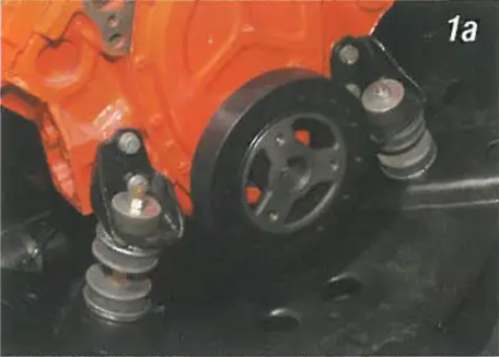
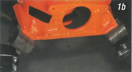
Image 1: All V8 and 6-cylinder engines were mounted at the front with two elbow brackets, studs and rubber grommets. The rear of the engine was held in with two mounts that bolted to the bellhousing for both automatic and standard transmissions.
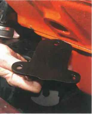
Image 2: The 1955-57 265 and 283 V8 engine blocks did not have the three bosses on each side fof side engine mounts. All 1958-later V8's were installed with side engine mounts.
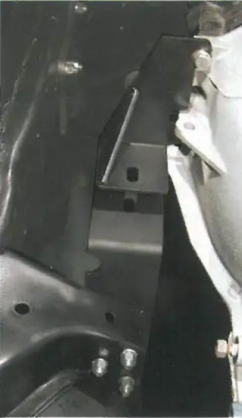
Image 3: If you wish to retain the original type front engine mounts, but use a late model TH transmission, bellhousing area mounts must be added along with a transmission cross member in order to give the driveline lateral stability. PIN 19-01 is a bracket kit that bolts to the two lower bellhousing bolts on each side of the transmission and to the frame horns where the original rear engine mounts bolted. The upper brackets bolt to the bellhousing using 3/8" X 1-1/2" bolts with lock washers. The lower brackets bolt to the frame with 3/8" X 3-1/4" bolts, flat washers, lock washers and nuts. If you are this installation in a 1955-56 equipped with an original 265 engine, you will want to use a PIN 19-68 starter in order to a starter mount location.
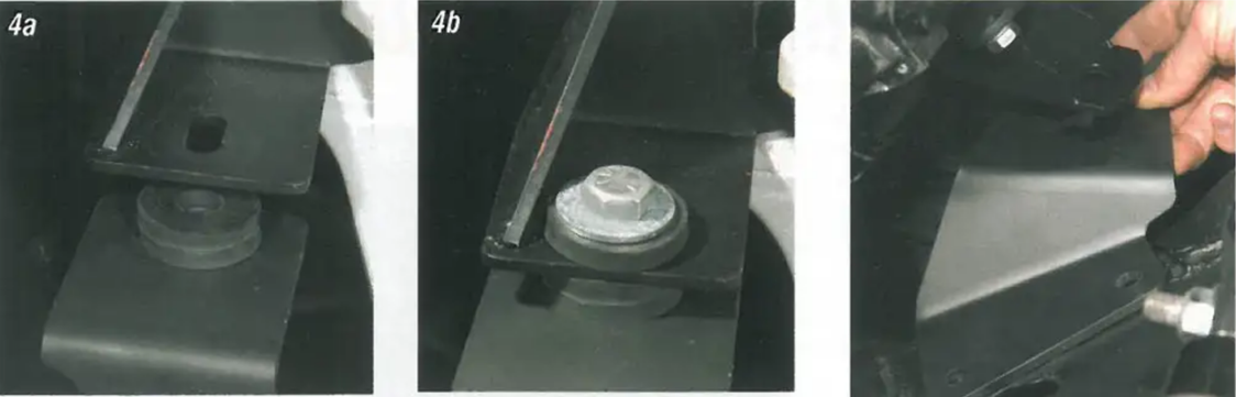
Image 4: The 19-01 kit includes eight rubber grommets. Two of the grommets fit between the upper and lower of the brackets. A 1/2" X 2" bolt with flat washers, grommets, nuts and cotter hold the two brackets together. Install the 1/2" bolt with a flat washer and grommet though the two brackets.
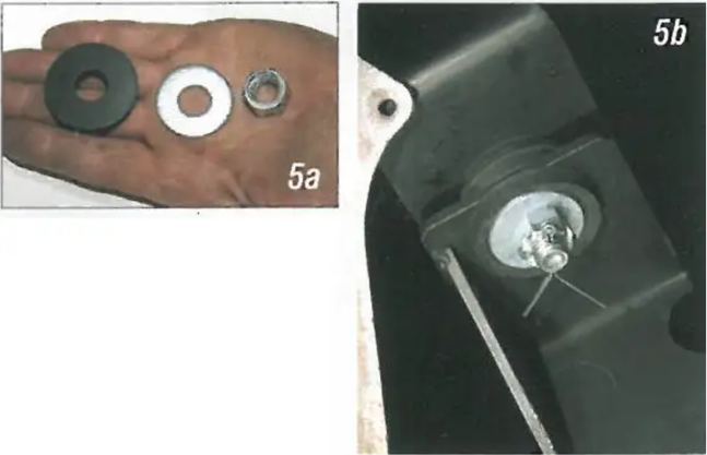
Image 5: The bolt is held in with a castellated nut and cotter. Install a grommet, flat washer, and nut. Tighten the nut and bolt so that the rubber grommets are squeezed out to the diameter of the flat washers and install the cotter.
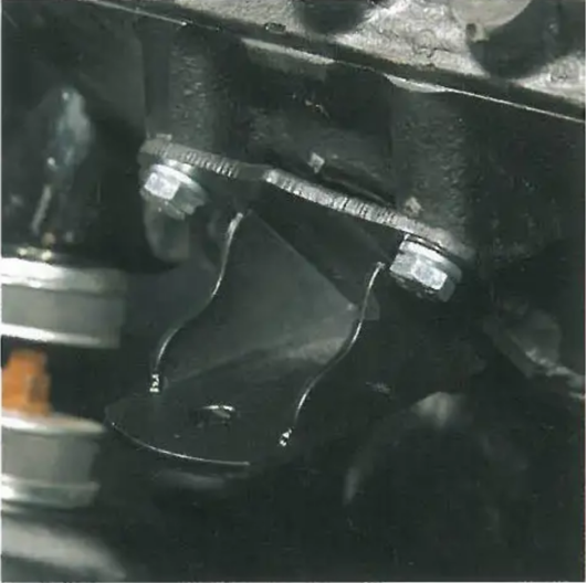
Image 6: If the original type front engine mounts are going to be deleted and side engine mounts installed, the bellhousing area mounts, PIN 19-01, will not be needed. The new side engine mounting kit, PIN 18-02, keeps the engine in the stock location with the brackets bolting to the main front engine crossmember. These mounts work on a 1 or 2-piece frame and allow for more exhaust header clearance. To install the new side mounts, we will use the stock front mounts to locate the engine. The side mount brackets bolt to the side of the engine using the 3 supplied 3/8" X 1" bolts and lock washers.
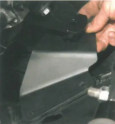
Image 7: The frame of the side mount brackets bolt to the front engine crossmember with (4) 3/8" X 1-1/4" bolts with flat washers, lock washers and nuts.
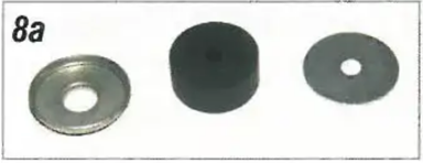
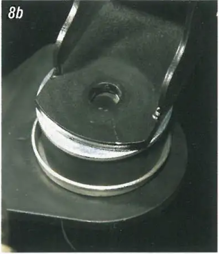
Image 8: Place the large rubber grommet between the engine bracket and frame bracket. This insulates any driveline vibrations from the frame and body. A cupped washer is used on the bottom of the grommet and a flat washer on the top.
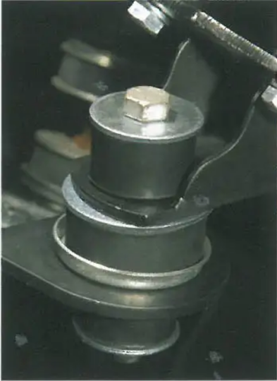
Image 9: A 7/16" X 3-3/4" bolt with small grommets, flat washers, and a lock nut hold the two halves of the side bracket together. After bolting the two brackets together, the lower frame bracket will be forced into the location on the front engine crossmember. Snug the nuts and bolts so that there is a firm "squeeze" on the rubber grommets.
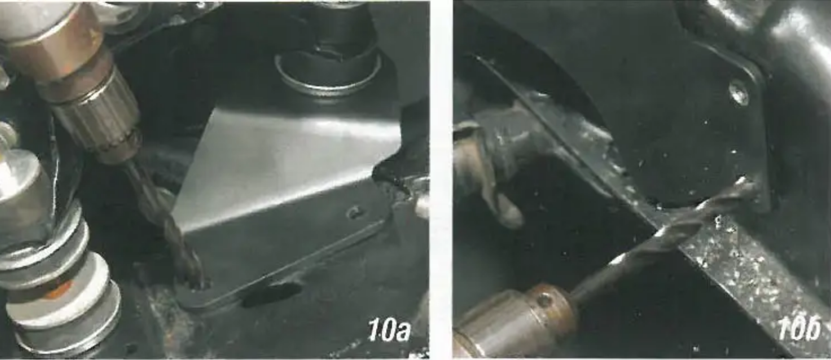
Image 10: With the frame brackets in use it as a guide and drill all four 3/8" holes in the engine crossmember fostall the 3/8" bolts, lock washers, and nuts to secure the brackets to the frame.
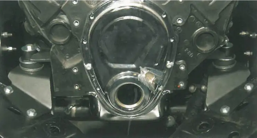
Image 11: With the new side engine mounts installed, the stock front engine mounts can be removed. This will allow for lots of room to install any accessories on the front of the engine.
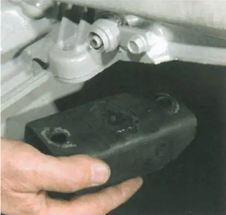
Image 12: A transmission crossmember must be installed to support the rear of the transmission with either method of engine installation; front or side. An intermediate rubber mount bolts to the rear of the transmission with two bolts; PIN 19-18 or PIN 19-26.
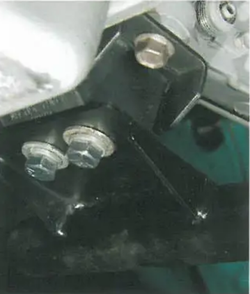
Image 13: Tubular transmission crossmember kit, PIN 19-153, may be used for any automatic or standard transmission. The crossmember bolts to the transmission mount with two 7/16" X 1" bolts with flat and lock washers.
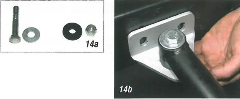
Image 14: The elbow mounting brackets for the transmission crossmember bolt to the crossmember with 1/2" X 3" bolts, with a thin washer, on the top of the crossmember and a thick washer and lock nut on the bottom of the elbow bracket.
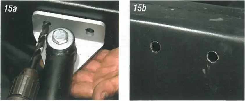
Image 15: Square up the crossmember in the frame. Using the elbow brackets as a guide, drill four 3/8" holes all the way through the frame rails. The transmission tailshaft height should be adjusted so the carburetor surface on the intake is approximately level.
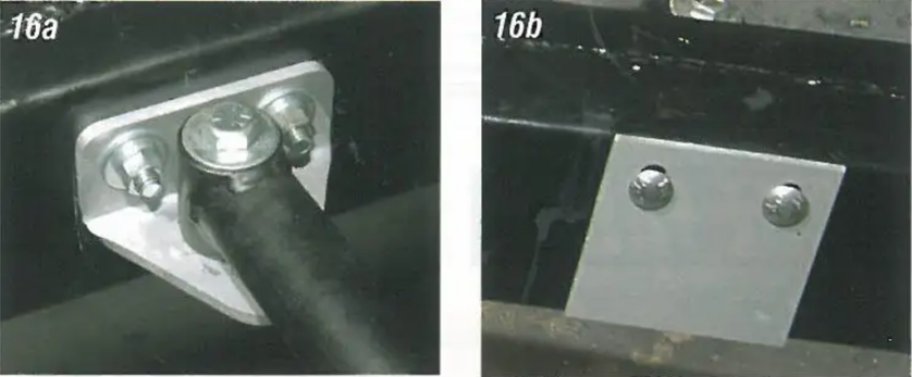
Image 16: The elbow brackets are attached to the frame with 3/8" X 5" carriage bolts with flat washers, lock washers, and nuts. There is a backing used on the outside of the frame where the carriage bolts through to keep the frame from collapsing and keep the bolts tight.
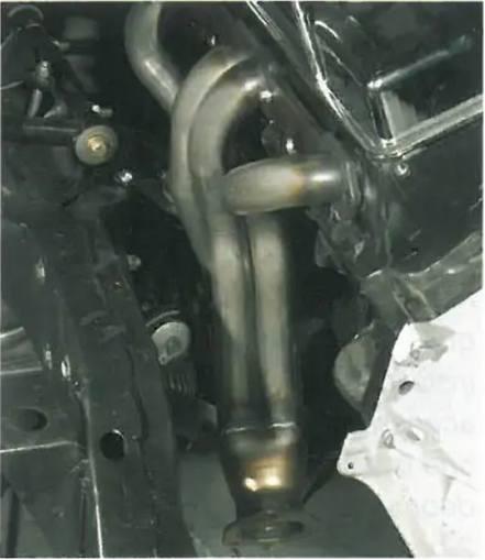
Image 17: With the engine side mounted and the transmission installed with a rear crossmember, you may even remove the original transmission frame horns for improved exhaust ground clearance.