Sales Techs Available: 1-877-305-8966
Talk to a Sales Tech
1-877-305-8966
M-F 8:30A-11P, Sat-Sun 8:30A-9P
1955-72 Serpentine Belt & Pulley System
With so many serpentine belt systems on the market, choosing one can be complicated and confusing. If you don't order every single accessory from the same manufacturer, it is likely the kit will not work. Many systems are over-engineered with two or three idlers, a belt that is long enough to wrap around your entire car and require more tools to install it than it takes to work on the space shuttle! The new Concept One Victory system is a work of art and is designed with simplicity, ease of installation, and function in mind. The kit is available in a brushed or natural (unpolished) aluminum finish and with or without power steering. The system bolts to the front of the engine block itself and does not require cylinder head bolt holes like other systems. This awesome kit is the way to update your small block or big block with a super simple yet attractive single belt drive system.
Parts List
- 57-177523-1 1955-72 Small Block Brushed Long Water Pump Serpentine Belt Pulley Kit With Power Steering
- 57-177522-1 1955-72 Small Block Polished Short Pump Serpentine Belt Pulley Kit With Power Steering
- 57-177527-1 1955-72 Big Block Brushed Short Water Pump Serpentine Belt Pulley Kit With Power Steering
- 57-177526-1 1955-72 Big Block Polished Short Water Pump Serpentine Belt Pulley Kit With Power Steering
Tools Needed:
- 1/2" Pull (Breaker) Bar
- 3/32" Allen Wrench
- 5/32" Allen Wrench
- 1/4" Allen Wrench
- 5/16" Allen Wrench
- 9/16" Wrench
- 5/8" Wrench
- Air Impact Wrench
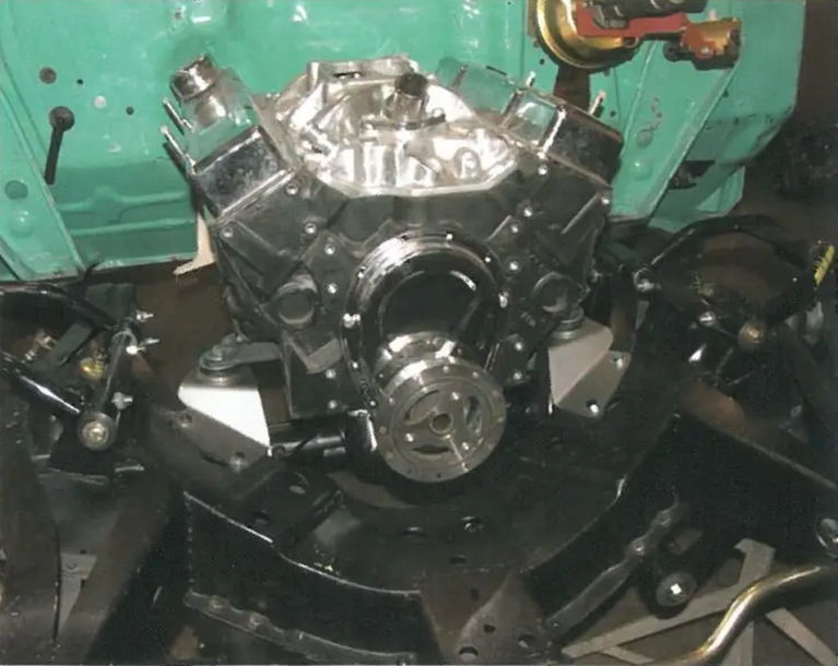
Image 1: The engine must be side-mounted using kit PN 57-131968-1 (small block) or PIN 57-170210-1 (big block) in order to install the serpentine system. The engine cannot be front-mounted.
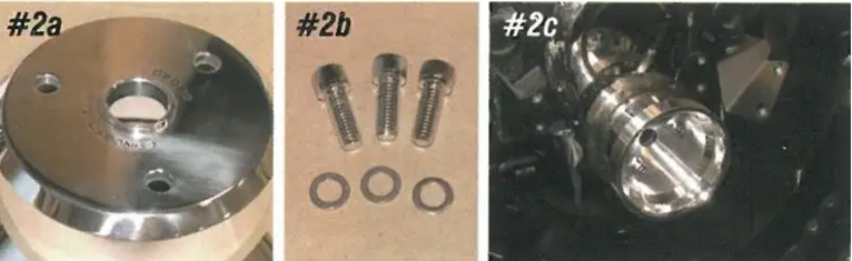
Image 2: The new billet crankshaft included in the kit has a collar on the backside that will center on the harmonic balancer. The harmonic balancer may have coarse or fine thread bolt holes. Three socket head bolts of each type are included to bolt the crankshaft to the balancer.
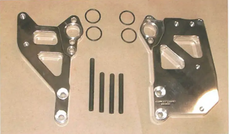
Image 3: There are left and right billet mountings that bolt to the front of the engine. All hardware and accessories bolt to these mountings are included. Since the mounting bolts to the engine block and not to the cylinder heads, the kit may be used with early model heads with no accessory holes.
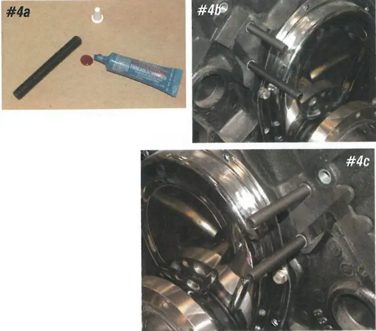
Image 4: Four 3/8" studs are supplied to hold the mounting in at the water holes. Three studs are 2-1/2" long, and one is 3-1/2" long. The driver's side of the engine uses two 2-1/2" long studs for the upper and lower water mounting, while the passenger side will use the 2-1/2" stud for the upper water mount and the 3-1/2" stud for the lower water mount. When installing the studs and all remaining mounting hardware in this kit, use a small amount of thread locker.
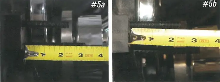
Image 5: With the studs installed, 2-1/4" of the shorter studs should remain out of the front of the engine block with 3" of the longer stud.
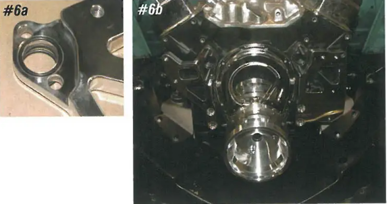
Image 6: There is an O-ring on the front and rear faces of the left and right mountings. Lubricate the O-rings with a small amount of Vaseline before installation. The water studs through the 3/8" holes above and below the water holes on the mountings.
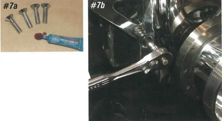
Image 7: Four 3/8" x 1-1/2" countersunk Allen head bolts hold the bottom of the mounting to the front of the engine block.
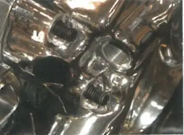
Image 8: Next, install the Edelbrock high flow water pump included in the kit onto the four studs. The studs should protrude out the front of the water housing by 1/2".
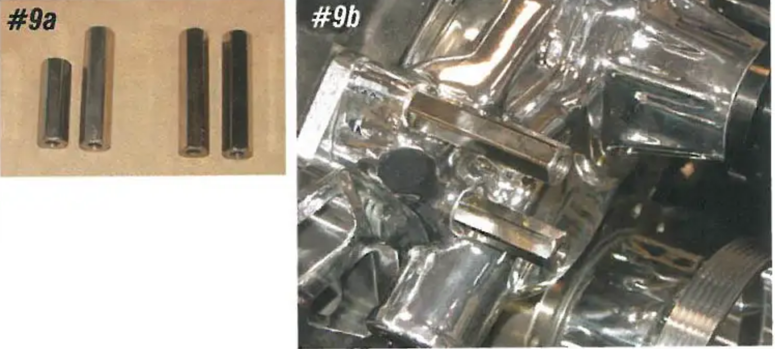
Image 9: There are four tall nuts that hold the water pump to the engine block. The two 3" long rail nuts are used on the driver's side of the engine. The 2-3/4" tall nut is for the upper side stud, and the 2" tall nut is for the lower stud on the passenger side.
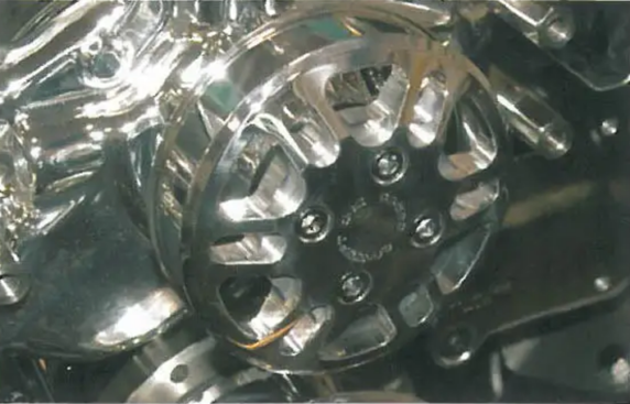
Image 10: The water pump is held to the water hub with four 5/16" x 1" Allen head bolts.
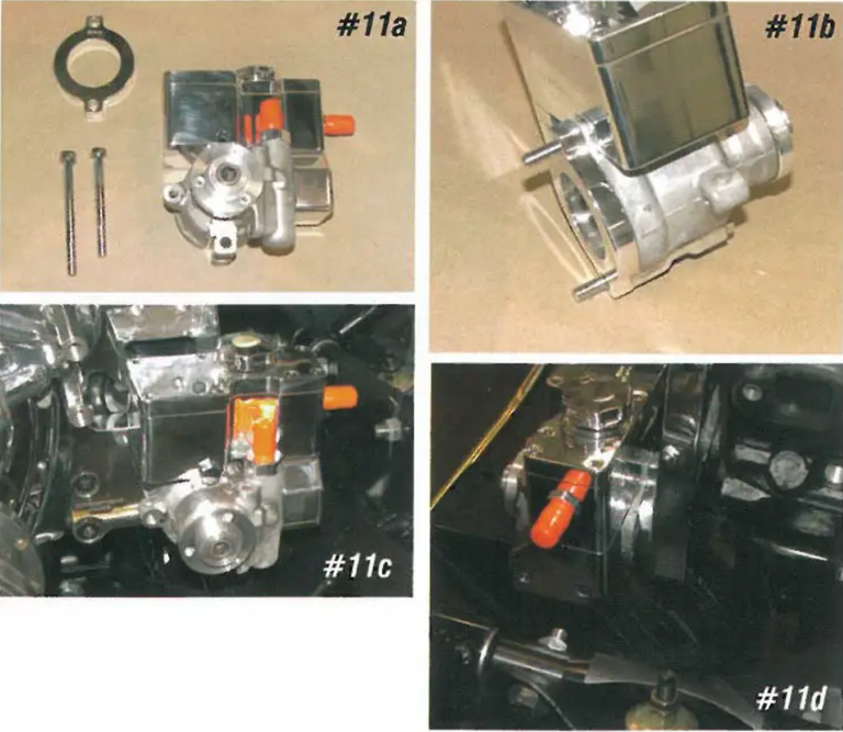
Image 11: If a kit with power steering is being installed, the system includes a GM Type-II pump, which is compatible with a 605, 670 (500) steering box or the CCI rack and pinion kit. The pump has a billet reservoir and 6 AN return fittings. The pump and spacer are mounted to the driver's side mounting and are held in place with a 5/16" x 4" upper bolt and a 5/16" x 3-1/2" lower bolt.
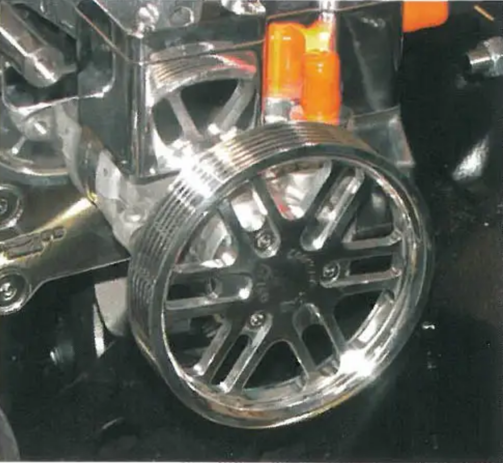
Image 12: The power steering pump is held to the mounting with three 1/2" x 3/4" Allen head bolts.
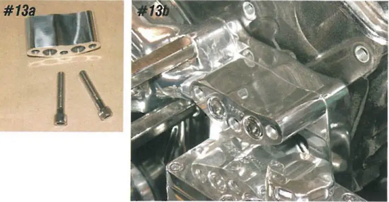
Image 13: The banana-shaped bracket is for the alternator and mounts to the driver's side mounting just above the power steering pump. The bracket is held to the mounting with two 3/8" x 1-3/4" Allen head bolts.
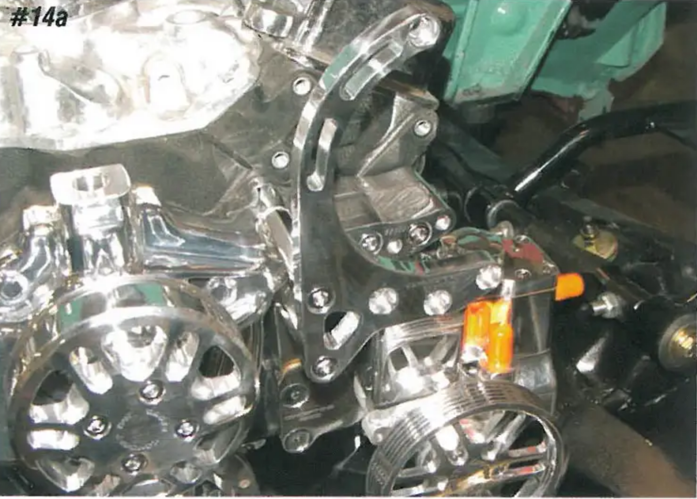
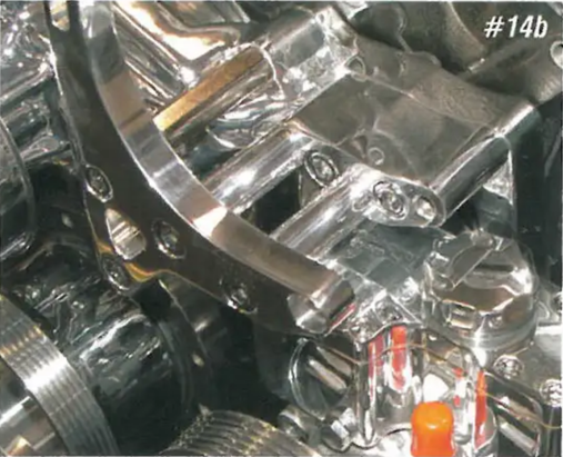
Image 14: Next, install the main alternator bracket. This bracket bolts to the two tall nuts on the driver's side and to the banana bracket. The main alternator bracket is held to the two tall nuts with two 3/8" x 1" Allen head bolts. Leave these bolts loose at this time. There are two 2" long spacers that fit between the main alternator bracket and the banana bracket. Two 3/8" x 3" Allen head bolts go through the main alternator bracket, the two 2" spacers, and bolt to the banana bracket. Also, leave these bolts loose at this time.
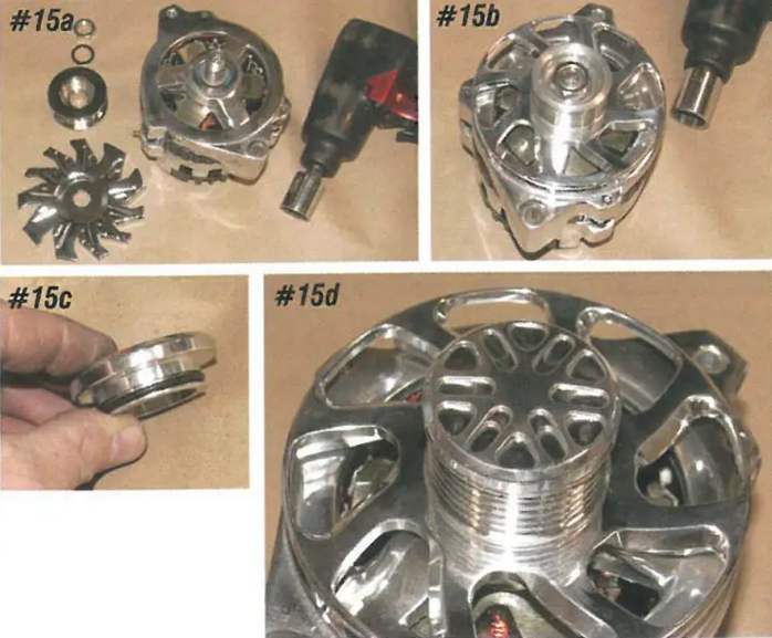
Image 15: The serpentine kit includes a new billet alternator cover and fan for the Tuff Stuff 100 amp alternator included with the kit. Using an air impact wrench, remove the chrome cover and fan and replace them with the new billet cover. The cover is held in place with an O-ring.
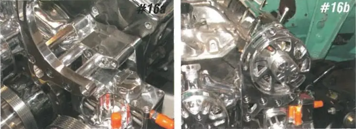
Image 16: The alternator is trapped between the main alternator bracket and the banana bracket. A 3/8" x 3" Allen head bolt is used at the bottom of the alternator, and an 8mm Allen head bolt is used at the top. With the alternator in place, tighten all mounting bolts.
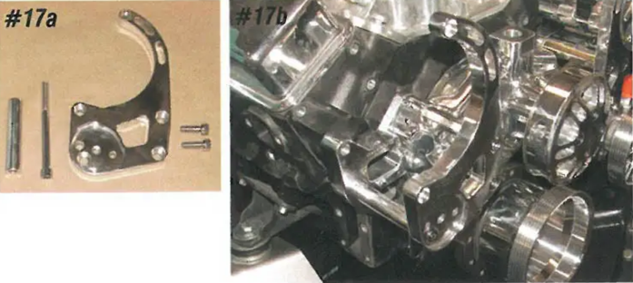
Image 17: The air conditioning compressor mounts on the side of the engine. The main AC bracket bolts to the two tall nuts and the mounting. Two 3/8" x 1" Allen head bolts hold the bracket to the tall nuts. Leave these bolts loose at this time. A 3-1/2" spacer fits between the main AC bracket and the mounting. A 3/8" x 4-1/2" Allen head bolt goes through the main AC bracket, through the spacer, and into the mounting. Leave this bolt loose as well.
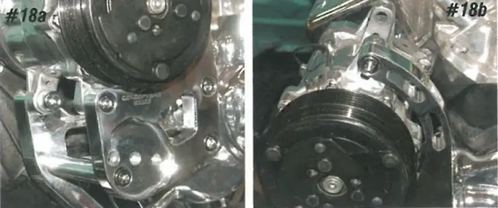
Image 18: A 7/16" x 1-1/2" bolt holds the lower rear ear of the compressor to the mounting, and an 8mm x 1-1/2" bolt holds the lower front ear of the compressor to the main AC bracket. The upper mounting ear of the compressor is bolted to the main bracket with an 8mm x 1-1/2" Allen head bolt. With these bolts installed, all the bolts can be tightened.
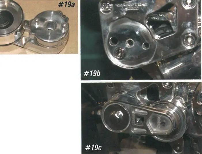
Image 19: The spring-loaded idler for the serpentine belt bolts to the front of the AC compressor bracket. There are two alignment pins that key into the front of the AC bracket. The idler is held to the bracket with a 3/8" x 2-1/2" bolt.
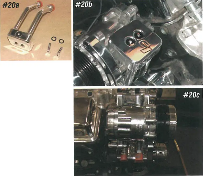
Image 20: The AC compressor includes a hard line manifold that routes the lines up under the compressor to the outside for a cleaner look. These fittings are 8-10 like most aftermarket AC kits.
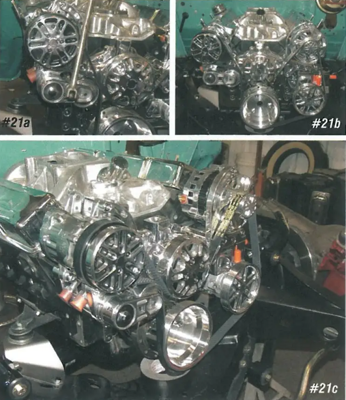
Image 21: Using an extension and a bar, press down on the idler and feed the serpentine belt around the pulleys.
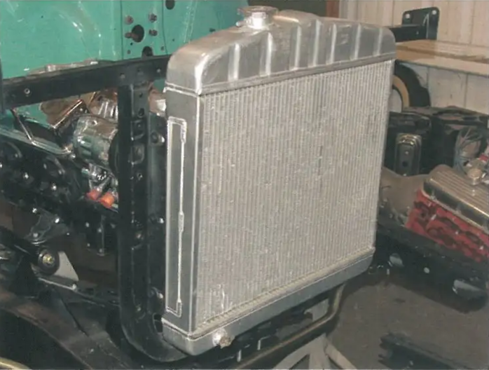
Image 22: When using the serpentine system, the radiator must be located in the 6-cylinder position in front of the core support. If you currently have a V8 radiator and V8 core support, you can easily move it to the 6-cylinder position using relocation kit PN 18-44. With the radiator in the 6-cylinder position, there is plenty of room for either a fan blade or an electric fan system. The serpentine systems also work well with our Griffin cross-flow radiators.