Sales Techs Available: 1-877-305-8966
Talk to a Sales Tech
1-877-305-8966
M-F 8:30A-11P, Sat-Sun 8:30A-9P
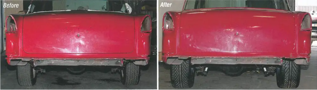
1955-57 Rear Leaf Spring Pocket Kit
Remember when a 15"X 8" wheel and a 9" wide tire were considered "big" on the back of your classic? These days, if you don't have at least a 17'' or larger wheel and a 10" to 13" wide tire, you might as well stay at home!
With the leaf springs in the stock location, the widest wheel that can be used is an 8". By installing the CCI leaf spring relocation kit, PIN 21-131, the leaf springs are relocated inside frame rails and up to a 9" wide wheel can be used with the stock fender wells and trunk tubs. To go to the next level, the rear trunk tubs can be moved in even with the frame rails (mini tub) and up to a 12" wide wheel may then be used!
In this article we will relocate the rear inner trunk tubs, install the new shock relocation bar for lowered cars and install the new double adjustable traction bars.
Parts List
- 57-133228-1 1955-1957 Chevy Rear Spring Pocket Kit to add bigger wheels and tires
- 57-161066-1 1955-57 Rear Shock Location Kit For Standard Height Or Lowered Cars 2-Piece Frame
- 57-161067-1 1955-57 Rear Shock Relocation Kit For Standard Height Or Lowered Cars 1-Piece Frame
- 57-133262-1 1955-57 Traction Bar Kit Use With Rear Spring Pocket Kit
- 57-133321-1 1955-57 KYB Gas Rear Shock Absorber
- 57-168688-1 1955-57 Non-Wagon Spare Tire Well Delete Panel
Tools Needed
- Welder
- Saws-All
- Metal Shears
- Ratchet
- Assorted Sockets
- Wrenches
Time Frame
- 16 Hours
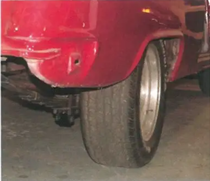
Image 1: With the rear leaf springs in the stock location, an 8" wide wheel with a 255 60R tire is really the biggest tire and wheel combination you can fit under the car.
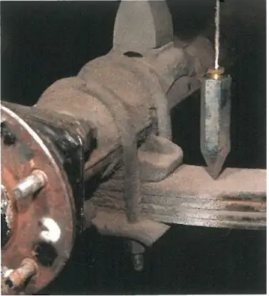
Image 2: By dropping a bob from the inner lip of the inner trunk tub down to the top of the leaf spring, you can see that the leaf spring intrudes into the wheel well 78". By relocating the leaf springs with the frame, this 78" is gained back so you can use up to a 9" wide wheel with plenty of clearance.
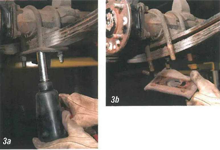
Image 3: To install PN 57-133228-1, Spring Pocket Kit, the rear end will need to be removed. Make sure the car is on safe jack stands or a lift and is supported in front of the forward leaf spring eye mount. Disconnect the driveshaft, rear emergency brake cables and the rear brake hose. Next remove the two rear shock absorbers. The rear end housing is held to the leaf springs with U-bolts and shock mounts. Remove the 3/4" nuts, shock mounts, and U-bolts.
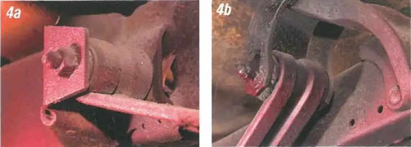
Image 4: The front of the leaf springs mount to the frame with a sheet metal spring-eye bracket welded to the frame. The rear of the leaf spring has a shackle mount bracket that is either welded or riveted to the frame.
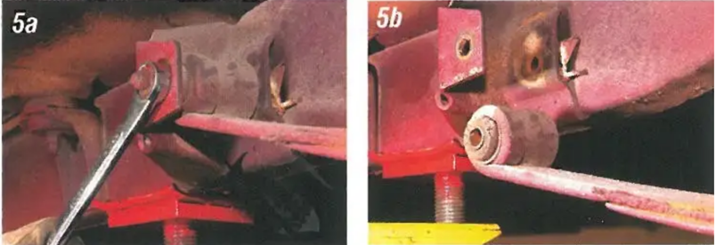
Image 5: Remove the forward spring eye bolt and drop the front of the leaf spring out of the bracket. Make sure to save the front spring eye bolts and nuts as they will be reused.
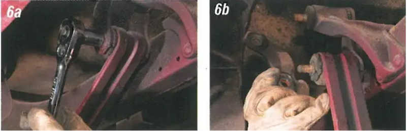
Image 6: At the rear, remove two shackle nuts and the outer shackle. This will allow the spring to be removed from the frame.
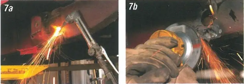
Image 7: Using a torch or an air chisel and grinder, remove the forward spring hanger from the frame.
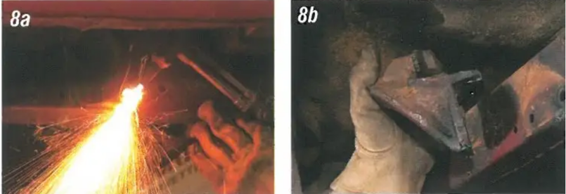
Image 8: Our frame had the rear shackle bracket riveted in. Using a torch, we cut the heads off the rivets and removed the bracket. There were two rivets on the side of the frame and two on the top.
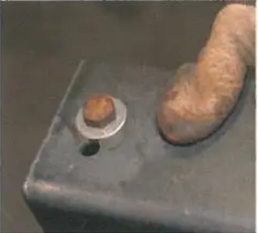
Image 9: There are two forward holes in the new spring. The lower hole is for 2-piece frames and the upper hole is for 1-piece frames. We have installed the factory front spring eye bolt into the lower hole of the with a standard 12" washer under the head of the bolt. This will help align the with the factory hole in the frame.
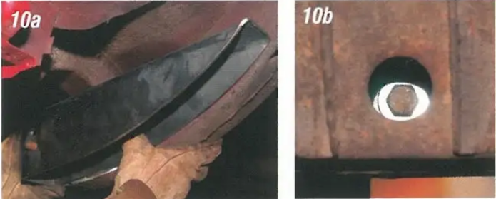
Image 10: Hold the on the outside of the frame and align the 12" washer with the factory hole in the frame where the front spring eye bolt through.
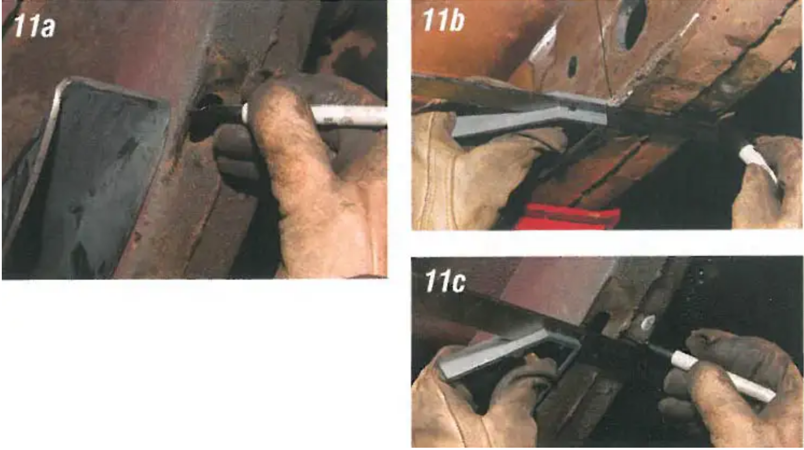
Image 11: Mark the frame where the is going to be welded in.
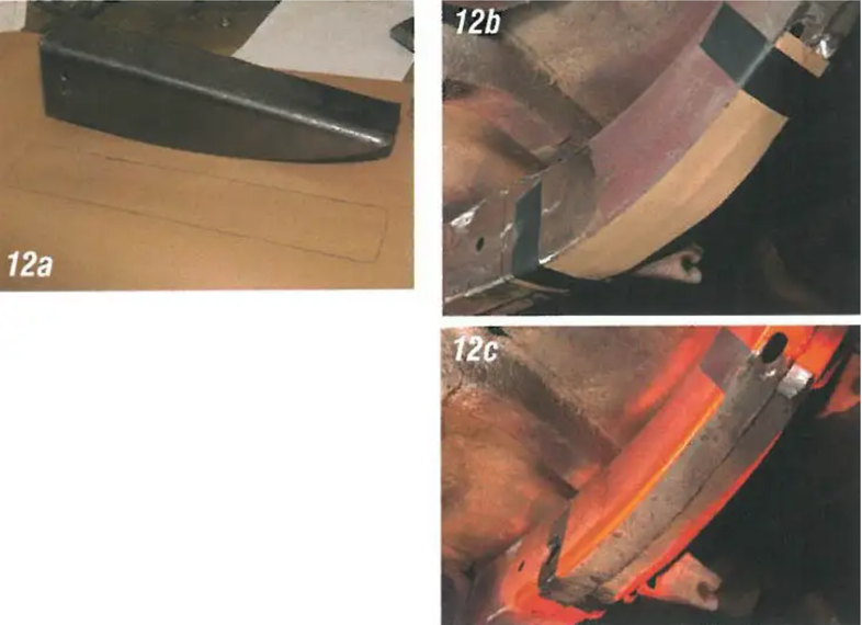
Image 12: We have found a safe and simple way to make sure we don't cut too much out of the frame for the spring. Make a template, lay it on the bottom of the frame and mark the frame.
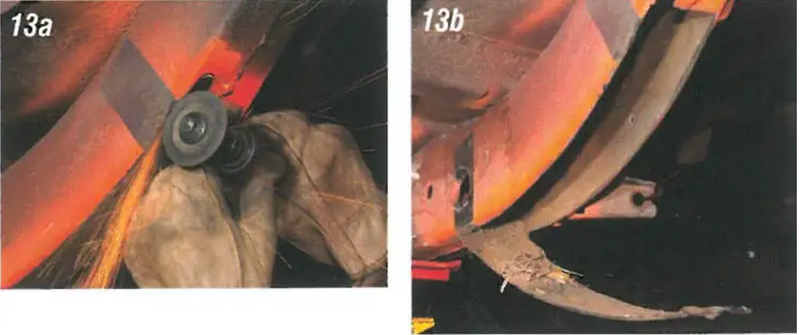
Image 13: Using a cut-off wheel or cutter, cut the bottom of the frame where the spring will be welded in. Make sure to leave of frame in for grinding to make a fit.
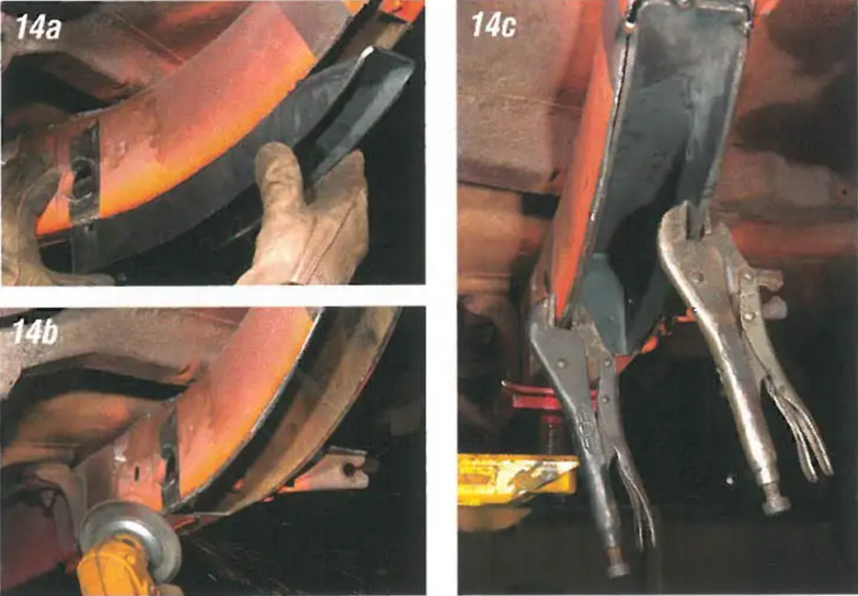
Image 14: Install the spring into the frame and check the fit. With the spring fitted in the frame, clamp the into.
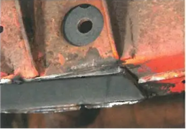
Image 15: When the new forward spring eye bolt hole in the spring is lined up with the original spring eye bolt hole in the frame, it may be necessary to trim the slightly to match the frame.
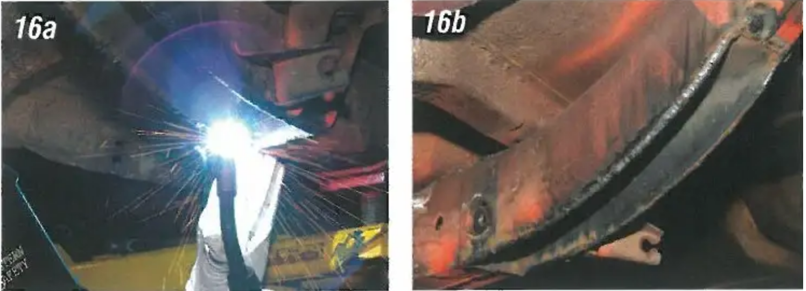
Image 16: Completely weld around the outer of the spring to the frame. Be sure to achieve a good "hot" weld as this is very important for strength.
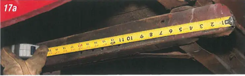
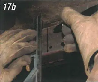
Image 17: The upper rear shackle bracket welds to the top of the frame. Measure from the rear of the frame forward 15" and mark the frame. This will be the center line for the upper shackle bracket.
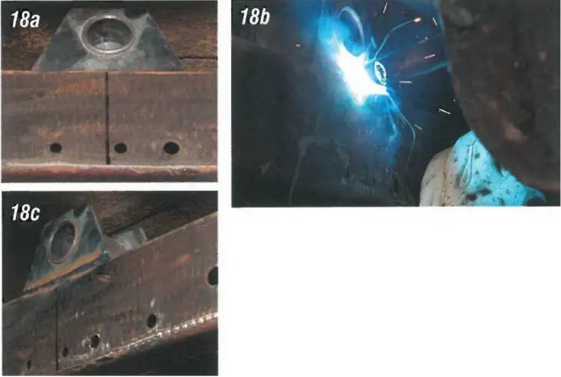
Image 18: Place the upper shackle bracket on top of the frame so that the center of the hole for the upper shackle bushings lines up with the mark on the frame. Tack weld the bracket to the top of the frame.
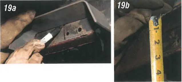
Image 19: The section of the frame just under the new upper shackle mount will need to be notched so the new shackle notch can be installed. This is supplied to box the frame in and add strength. Center the with the upper shackle mount and mark the frame where it will need to be cut. Make sure there is 1-1/4" (vertical) of stock frame left between the top of the new frame channel and the top of the frame.
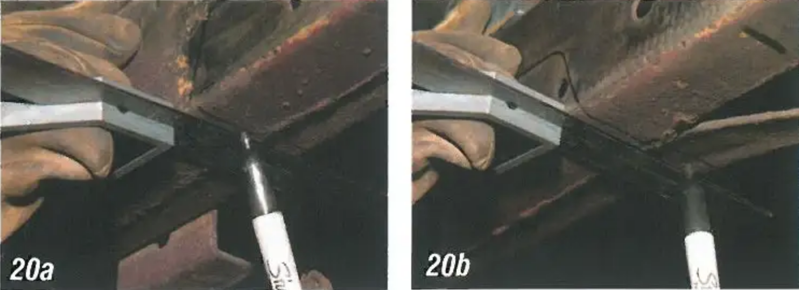
Image 20: After marking the outside of the frame, use a square to transfer the marks to the bottom and inside of the frame.
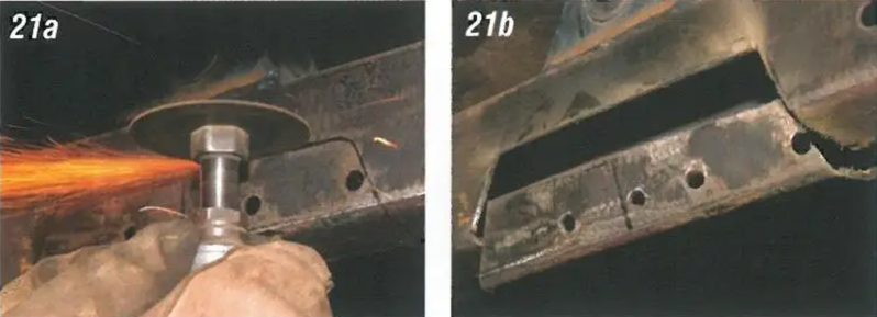
Image 21: Use a cutter or cut-off wheel to notch the frame for the new channel.
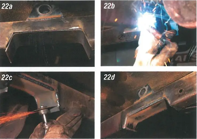
Image 22: Fit the new channel into the frame and weld it into. Again, a good "hot" weld is required for maximum strength.
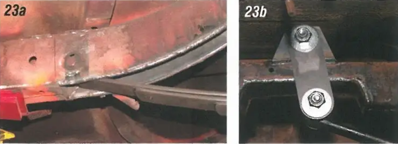
Image 23: The stock leaf springs or lowering springs will work with the new spring kit. We are going to install new standard height 5-leaf springs PN 57-133302-1. The front leaf spring-eye fits into the new forward spring. The rear spring-eye attaches to the new shackle and bushings included in the kit.
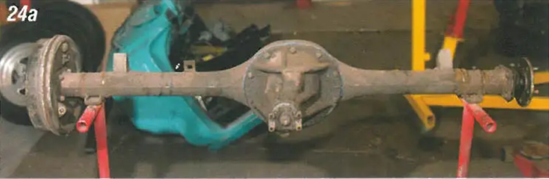
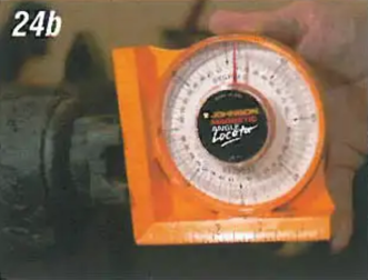
Image 24: With the leaf springs now moved in with the frame rails, the spring on the rear end housing will need to be moved inward to match the leaf spring. Before removing the old spring, the original angle must be determined. Place the rear end on a set of jack stands or saw horses and using an angle finder check and record the angle.
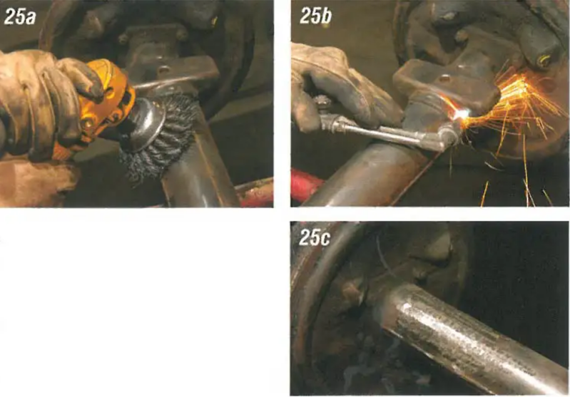
Image 25: The factory spring were spot welded to the rear end housing. Use a torch or cutter to remove the.
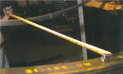
Image 26: To determine the location of the new spring included in the kit, measure from side to side on the leaf spring center.
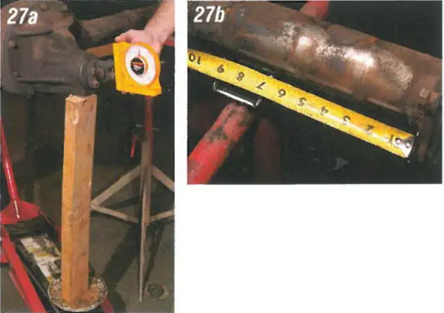
Image 27: Place the new spring and rear end housing on the jack stands and set the angle. Make sure the left and right have the same measurement from each axle flange. This will the rear end in the exact center of the frame.
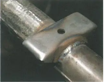
Image 28: With the angle set and the in the location, tack weld them into. Next turn the rear end over and weld the spring solid to the rear end housing.
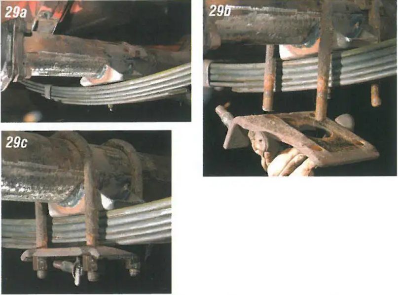
Image 29: Set the rear end back onto the leaf springs. Using the stock U-bolts, nuts, and lower shock bolt the rear end into.
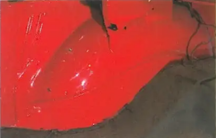
Image 30: With the leaf springs relocated, up to a 9" wheel may now be used. We are going to go that extra step and move the inner trunk tubs inboard even with the frame rails. This will allow up to a 12" wide wheel and 13" wide tire to be used!
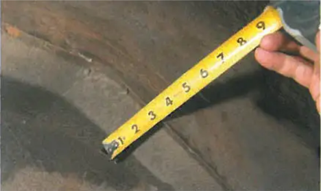
Image 31: The inner trunk tubs can be moved in (viewed here from underneath) 3" side; even with the frame for more tire clearance.
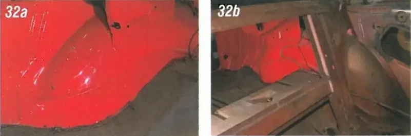
Image 32: The section of the trunk tub that will be moved will be from the inner trunk wall to 3" inboard from where the wheel well attaches to the trunk wall, floor, and under the seat.
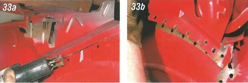
Image 33: The trunk hinge boxes have a lip on the bottom that is welded to the top of the tubs. Using a saw, cut the lip, leaving a lip on the bottom of the box. Then drill out the spot welds that secure the hinge box bracket to the tub.
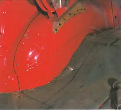
Image 34: Mark the trunk tub and floor where the cuts will be made. Measure in from the trunk wall 1". Mark the trunk floor 3" inboard of the tub. This will allow the factory tub to trunk floor seam to be reused. This will save a lot of work and will look nice and clean.
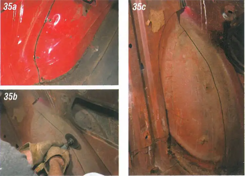
Image 35: Using a cut-off wheel or saws-all cut around the entire trunk tub. The support from the tray to the under the seat floor will need to be cut also.
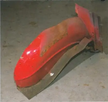
Image 36: Once everything is cut loose, the trunk tub can be removed. All of the raw edges will need to be cleaned up with your grinder before welding.
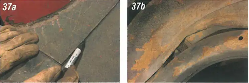
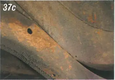
Image 37: Place the cut tub and trunk floor in. This will the inner lip of the tub even with the frame rail underneath. Now mark the trunk floor where it needs to be cut.
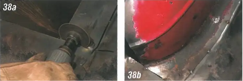
Image 38: Using a cut-off wheel, cut the trunk floor. Place the cut section of tub and trunk floor in and tack weld.
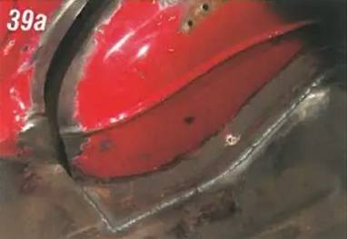
Image 39: If the fit is satisfactory, weld the relocated floor to the original floor. After the floor is solidly welded in, weld the 1" lip you left on the bottom of the hinge box to the top of the tub.
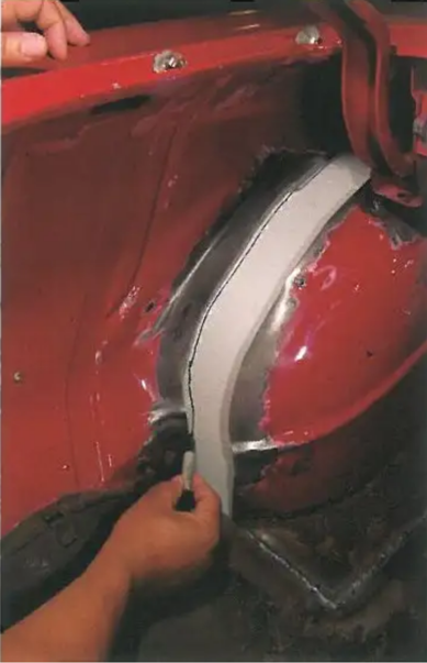
Image 40: Using a piece of cardboard, mark the opening between the stock outer trunk wall and the relocated inner tub.
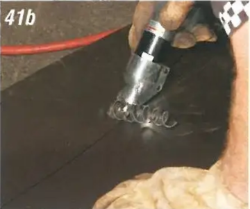
Image 41: Using the cardboard as a template, trace it out on a piece of 16-gauge sheet metal. Use a pair of metal shears to cut out the filler.
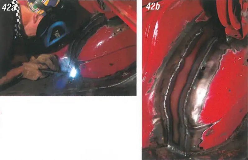
Image 42: Once the fit of the filler is satisfactory, weld the entire piece into place.
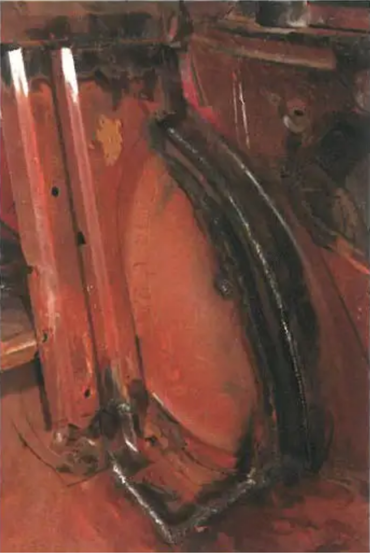
Image 43: With the filler welded into the rear support may be welded back into place.
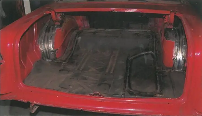
Image 44: With the tubs moved in even with the frame, there will be enough room to use up to a 12" wide wheel. We have also installed our new spare tire well delete PN 57-154085-1.
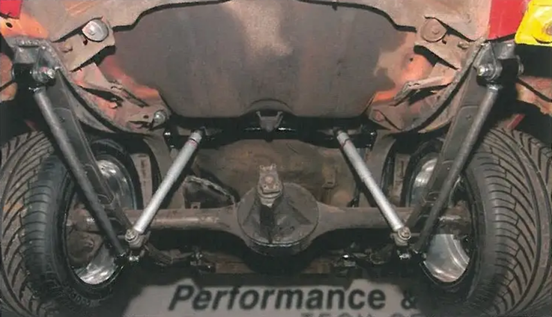
Image 45: We also installed the new shock bar for the lowered cars and two-piece frames, PIN 57-161066-1, and the new double adjustable traction bar kit, PIN 57-133262-1, for the spring kit along with the KYB gas charged rear shocks, PIN 57-133321-1. The rear end is now really tied into this car nicely and should give great traction and handling characteristics.
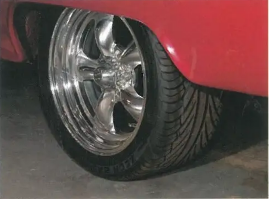
Image 46: We decided to use the American Torque Thrust wheels in 17'' X 9-12" with 6-12" backspacing. The 6-12" backspacing indicates how much wheel there is from the axle face of the wheel inward. By using a wheel with a 6-12" backspacing, the stock-length rear end may still be used. This wheel makes this upgrade very economical since no rear end or axle mods are needed. You can use up to a 9-12" wheel without narrowing the rear end. Anything wider will require a narrowed rear end housing such as a 9-inch Ford. The front wheel we chose is a 17" X 7" with 4" backspacing. The 4" backspacing works on the front of a '55-'57 with disc or drum brakes.
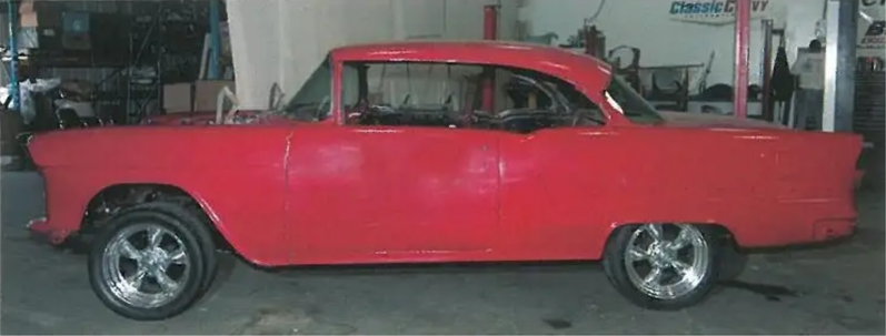
Image 47: There is nothing like a set of wheels and tires to change the whole look of a car!