Eckler's Catalogs Available Now!
1955-57 Hydraulic Clutch Installation
When automobiles were first built in the 1880's, they had mechanical clutch linkage. Your manual transmission classic '55-'57 still has clutch technology that is 125 years old! It's time to update that antiquated clutch linkage with a state-of-the-art hydraulic clutch system. Installing a hydraulic clutch system will not only remove all of that ugly, clunky clutch linkage and clean up the engine compartment and firewall, it will also give you increased clearance in the engine compartment for custom headers and exhaust. The new Hydraulic Clutch System includes a small master cylinder that mounts up under the dash out of sight. Our system uses a hydraulic release bearing so that the mechanical clutch fork in the bellhousing is also removed for an even cleaner installation. This system will work with a three finger type or a diaphragm type.
Parts List
- 57-173485-1 1955-57 Hydraulic Clutch System With Muncie 4-Speed Jerico Transmission
- 08-501 Saginaw Hydraulic Clutch System
- 57-173487-1 1955-57 Hydraulic Clutch System With T10 4-Speed Richmond 5 6-Speed Transmissions
- 57-173488-1 1955-57 Hydraulic Clutch System With T5 5-Speed Transmissions
Tools Needed
- 1/2" Wrench
- 9/16" Wrench
- 3/8" Ratchet
- 1/2" Socket
- 9/16" Socket
Time Frame
- 4 Hours
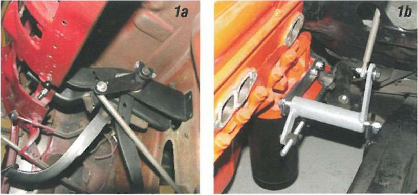
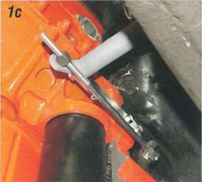
Image 1: The mechanical clutch linkage starts at the clutch swing arm under the dash with a rod that routes through the firewall and connects to the cross shaft between the frame and the bellhousing bracket. A second rod connects the cross shaft to the clutch fork. This all works fine when everything is in good condition, but once one part starts to wear, the complete system can become sloppy. The clutch linkage also takes up a lot of engine compartment room, which can limit your choice of headers.
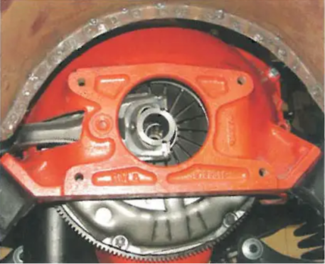
Image 2: The clutch fork fits through a hole in the bell housing on the driver's side and connects to the mechanical release (throw out) bearing. The new hydraulic clutch system eliminates all of the clutch linkage, clutch fork, and release bearing.
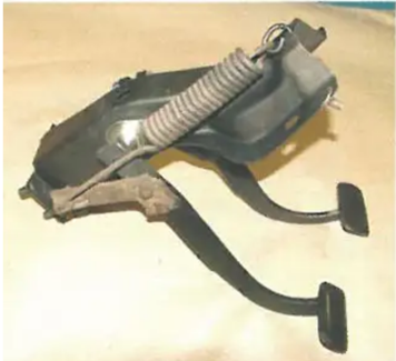
Image 3: The hydraulic clutch master cylinder mounts to the top of the brake swing arm assembly under the dash. By mounting the master cylinder under the dash and not out on the firewall, the engine compartment will remain nice and clean. On 1955 and 1956 cars, one hole must be drilled, and on 1957 cars, two holes must be drilled in the brake swing arm assembly. To complete this, the assembly will need to be unbolted and removed from the car.
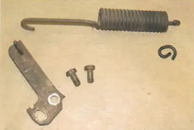
Image 4: The stock clutch swing arm has a return spring and bracket that will need to be removed. The return spring bracket is bolted to the clutch arm with two 9/16" bolts.
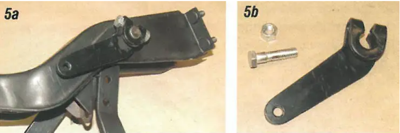
Image 5: The clutch arm is splined to the clutch shaft and secured with a 9/16" bolt, nut, and lock washer. The stock arm will be replaced with a new billet arm for the hydraulic master cylinder.
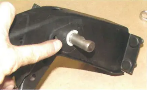
Image 6: Before installing the new clutch arm, make sure the bushings on the clutch shaft are in good shape. If the shaft is wobbly, the bushings are bad. To replace the bushings, slide the shaft out of the sleeve and install two PIN 57-131171-1 bushings. Be sure to lightly grease the bushings.
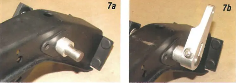
Image 7: Install the aluminum bushing in the kit onto the clutch arm shaft. Next, install the billet aluminum clutch master cylinder arm. Make sure the offset of the arm is toward the left (driver side) of the assembly. The arm is held to the shaft with an Allen head bolt and lock nut that will overlap the flat cut in the clutch shaft just like the original arm.
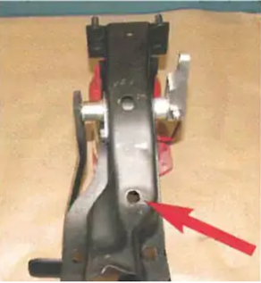
Image 8: The clutch master cylinder bracket bolts to the top of the assembly with two 9/16" x 1" bolts, lock washers, and nuts. There is an existing hole on the 1955 and 1956 assembly that can be used for one of the mounting holes for the clutch master cylinder bracket.
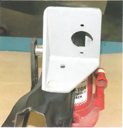
Image 9: Bolt the bracket to the top of the assembly and square up the front of the bracket to the new clutch arm.
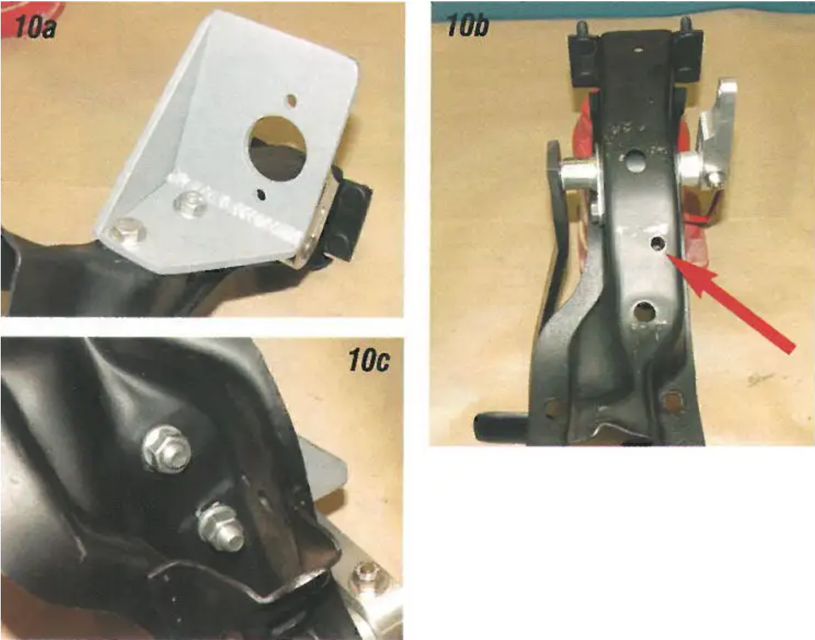
Image 10: Using the bracket as a guide, drill the second 3/8" hole in the assembly and bolt the bracket in.
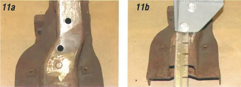
Image 11: On the 1957 assembly, both 3/8" holes must be drilled for the clutch master cylinder bracket. The rear edge of the bracket should be located 2-7/8" from the rear edge of the assembly. The original support rods from the assembly to the cowl will no longer be used.
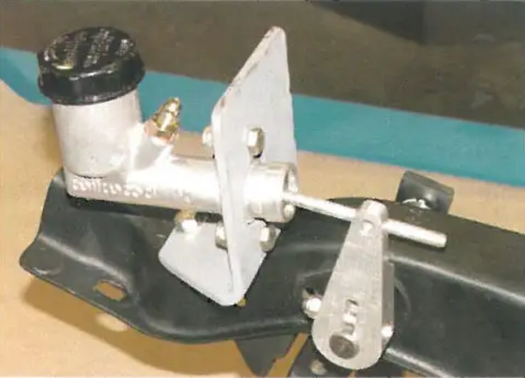
Image 12: The clutch master cylinder bolts to the master cylinder bracket with two 5/16" X 1-1/4" bolts with lock nuts.
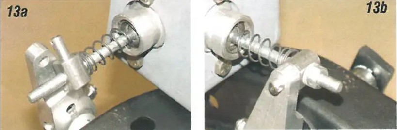
Image 13: The master cylinder is equipped with a threaded shaft. The 3" long spring should be installed onto the shaft first. Screw the coupler onto the shaft to connect the master cylinder to the clutch arm. Make sure the flat side on the coupler is facing away from the master cylinder.
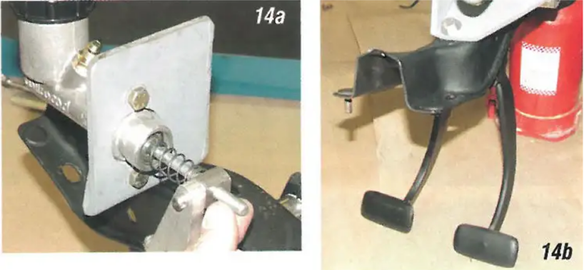
Image 14: The shaft for the master cylinder can be turned so that clutch height can be adjusted. This can be done on the bench.
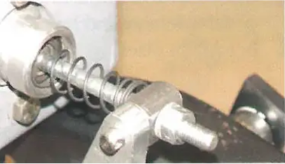
Image 15: Once the clutch height is set, lock the master cylinder to the coupler using the 5/16" fine thread nut and flat washer.
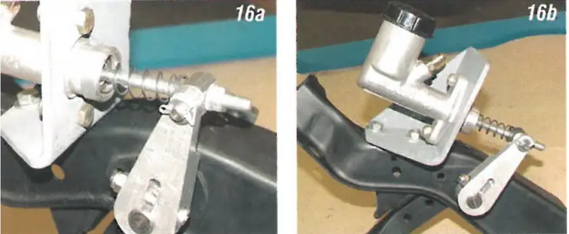
Image 16: Install the cotter and washer to hold the coupler to the clutch arm. The assembly is ready to be installed back under the dash.
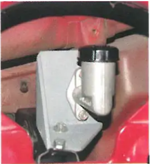
Image 17: With the assembly back in the car, the clutch master cylinder will be to the right of the gauge cluster allowing clearance for the stock gauge cluster as well as any aftermarket gauge cluster. The stock wiper transmission cables and the updated Raingear system will clear as well.
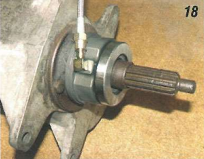
Image 18: The hydraulic release bearing fits on the front bearing retainer on any three, four, five, or six-speed standard transmission.
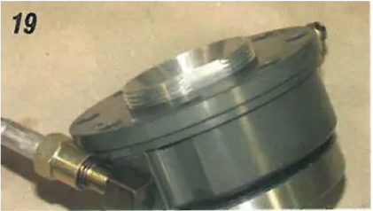
Image 19: The release bearing is adjustable in length so that it can be used with a diaphragm or three-finger type clutch. A set collar on the release bearing may be adjusted in or out to set the clearance between the release bearing and the clutch fingers.
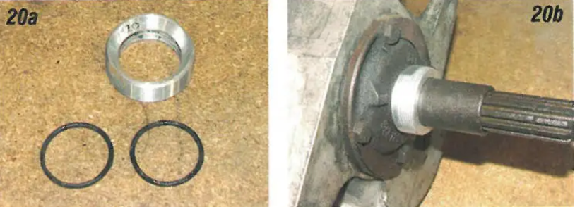
Image 20: The adjusting collar for the release bearing has two o-rings on the inside bore so that it will not spin. Lubricate the o-rings with a light oil and install the collar onto the front bearing retainer. The beveled side of the collar installs against the transmission face.
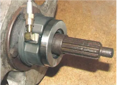
Image 21: Next, install the release bearing onto the adjusting collar by turning the bearing clockwise until the rear face of the bearing bottoms out on the front bearing retainer bolts.
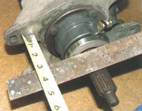
Image 22: Measure the clearance between the release bearing and the clutch fingers. To make the release bearing work, there must be no less than .100" and no more than .300" between the bearing and the fingers. First, measure the distance from the front of the gearbox to the front of the release bearing. Our car had a measurement of 3".
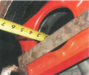
Image 23: Next, measure the distance from the face of the bellhousing to the fingers on the clutch. Our car had a measurement of 2-7/8". By subtracting 2-7/8" from the 3" measurement, we find that we have 1/8" (.125") clearance between the release bearing and the fingers of the clutch. This is within the tolerances required for the release bearing. If your measurement is not .100" to .300", turn the entire bearing assembly clockwise or counterclockwise full turns until the measurement is obtained.
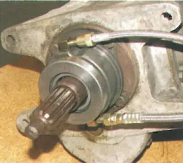
Image 24: There are two fittings on the release bearing. The upper fitting is for bleeding the hydraulic system. A 12" long 4 steel braided hose is installed on this fitting with a bleeder fitting on the end. The lower fitting is for the supply hose from the master cylinder. The kit includes a 60" long 4 Teflon steel braided hose that connects the release bearing to the clutch master cylinder. Connect the straight end of the 4 hose to the lower fitting on the release bearing.
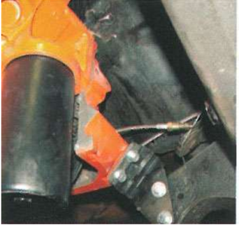
Image 25: With the two hoses connected to the release bearing and the bearing installed onto the front bearing retainer, the transmission may be installed. Feed the two hoses out through the hole in the side of the bellhousing where the clutch fork was installed and bolt the transmission into place.
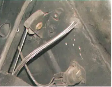
Image 26: The supply hose can be routed through the firewall in any desired location. Make sure the hose is kept away from any moving or hot exhaust. The kit includes a grommet so that the hose will be insulated as it passes through the firewall.
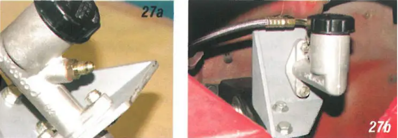
Image 27: The 90-degree end on the hose from the release bearing connects to the 4 fitting on the master cylinder.
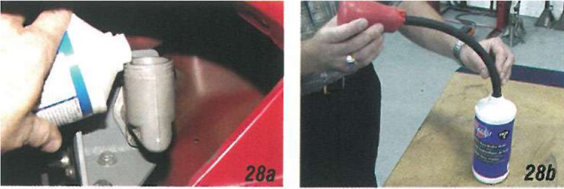
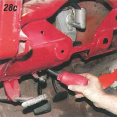
Image 28: With everything installed, it is time to add brake fluid to the clutch master cylinder. Use ONLY DOT 3 brake fluid and not silicone brake fluid. Using silicone brake fluid will damage the release bearing and void any warranty: If the gauge cluster is removed, there is room to get a container of brake fluid up to the master cylinder top to fill the master cylinder. Fill it to within 1/2" of the top. If there is not enough room to get a container of brake fluid up to the master cylinder, use the supplied squeeze ball and hose to fill the master cylinder. Spread a garbage bag out on the floor of the car to protect the carpet.
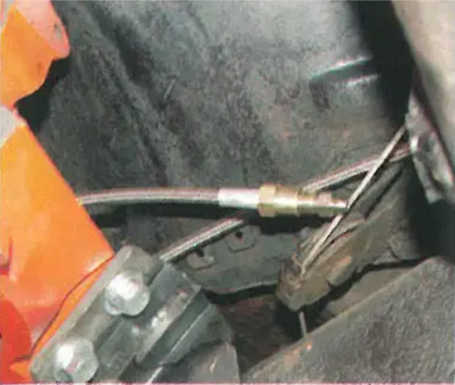
Image 29: The clutch master cylinder will bleed just like a brake master cylinder. With the master cylinder filled, pump the clutch pedal four or five times and hold the pedal to the floor. Now open the bleeder on the 4 hose from the release bearing allowing the air to escape. Do this several times until all the air is bled from the system.
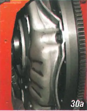
Image 30: Once all the air has been removed, the release bearing will move forward 1/2" to disengage the clutch. This amount of movement is enough to adequately disengage a three-finger or diaphragm style clutch. Using a couple of zip-ties, tie the two 4 steel braided hoses together so that the hoses cannot make any contact with the exhaust when the engine is running. Enjoy your new smoothly operating clutch system using 21st-century technology!
Conclusion:
Upgrading your classic '55-'57 vehicle with a state-of-the-art hydraulic clutch system is a smart choice. It not only enhances the performance and driving experience but also cleans up your engine compartment and provides more flexibility for custom modifications. Say goodbye to outdated mechanical clutch linkages and hello to modern hydraulic technology.