Eckler's Catalogs Available Now!
1955-66 Ididit Tilt Steering Column Installation Update
The ididit company now manufactures new steering columns for all 1955-1966 Chevy full-size cars. A brand new tilt column is the final touch when installing a late model steering system on your classic. These columns can be installed with the stock steering box as well. For a more original look, install the steel column and to match your interior. Or for a real custom look, install the brushed aluminum or chrome column. Columns are available for column shift or floor shift cars. You may use any late model or aftermarket steering wheel as a bolt-on, or your original wheel may be installed by using adapter PIN 53-202. This article will cover a 1955-56 installation. Other types and years of tilt columns are very similar.
Parts List
- 57-140799-1 - 1955-57 Replacement Steering Column Firewall Bracket Clamp
- 57-131195-1 - 1955, 1956, 1957 Automatic Transmission Firewall Seal For Bel Air, Nomad, 210 150 All Models
- 05-49 - 1955-72 Courtesy Light Delay Module Kit
- 57-130860-1 - 1955-56 Automatic Transmission Floor Seal
- 57-130845-1 - 1955-56 Steering Column To Dash Rubber Seal
- 57-135506-1 - 1955-57 Firewall Insulation Pad Fastener Set
- 57-130990-1 - 1955-56 Automatic Transmission Shifter Indicator Wire
- 57-133752-1 - 1955 Tilt Column Adapter Wiring Harness
- 57-133753-1 - 1956 Tilt Column Wire Adapter
- 57-133754-1 - 1957-58 Tilt Column Wire Adapter
- 57-159995-1 - 1955-1956 Chevy Bel Air Steering Wheel 15" With Horn Ring custom upgrade over stock
- 57-159996-1 - 1957 15" Steering Wheel 210 Bel Air small diameter steering wheel over stock
- 57-170911-1 - 1955-57 Impala Style Replacement 15" Diameter Steering Wheel
- 57-137036-1 - 1956-57 Firewall Pad Fastener Installation Tool
- 57-160378-1 - 1955-68 Original Steering Wheel To Late Model Column Adapter Kit
Tools Needed
- 12" Wrench
- 7/16" Wrench
- 12" Socket and Ratchet
- Phillips Screw Driver
Time Frame:
- 3 Hours
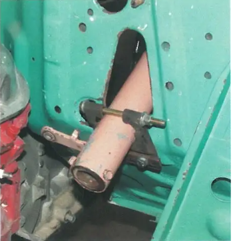
Image 1: The original steering column out the firewall about 3-1/2".
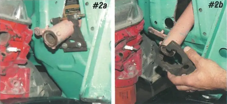
Image 2: The lower of the column mast jacket originally attached to the firewall with a squeeze clamp that is bolted to the engine compartment side of the firewall with two 5/16" bolts. Remove the bolt at the top of the clamp, and the two bolts that hold the clamp to the firewall, and the clamp can be removed from the mast jacket.
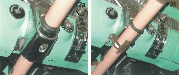
Image 3: The top of the mast jacket attaches to the dash with a clamp that is held to the dash with two studs and nuts. To access the clamp, remove the lower mast jacket cover. The cover is held in with an 8 sheet metal screw.
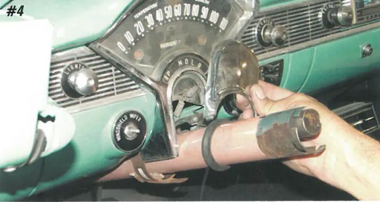
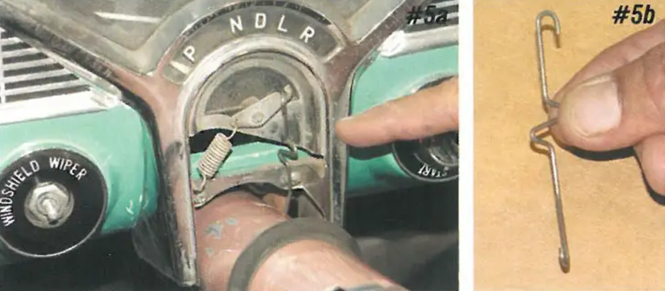
Image 4-5: The upper mast jacket cover snaps into the front of the instrument bezel. On automatic transmission cars, an indicator wire PIN 57-130990-1 runs from the shift tube to the shift indicator. This wire must be removed before removing the mast jacket. The indicator is spring-loaded, and the indicator wire simply hooks to the shift tube and indicator arm.
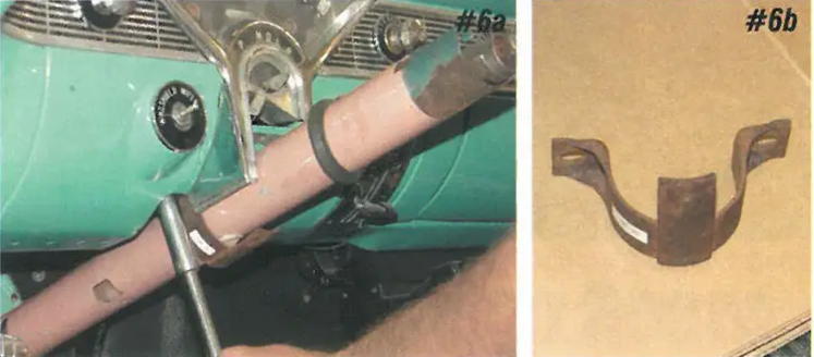
Image 6: Remove the two 1/2" nuts that hold the mast jacket to the dash clamp. The clamp will drop down, and the mast jacket may be removed.
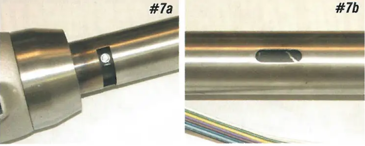
Image 7: The ididit tilt columns manufactured for the 1955-57 column shift cars have a ring on the shift tube so that the shift indicator wire can be reconnected. There is also a slot cut in the bottom of the column that will match up with the tab on the mast jacket to dash bracket.
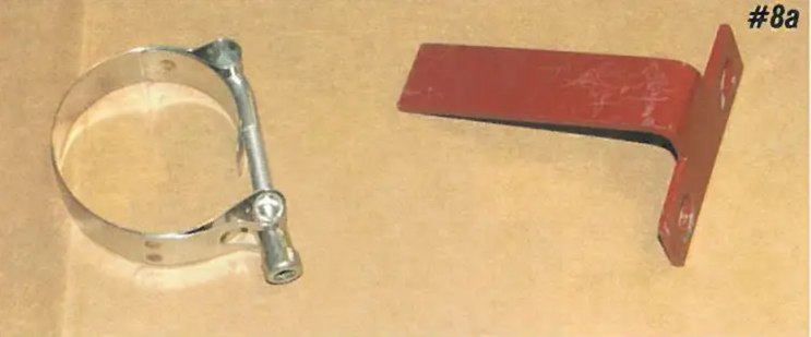
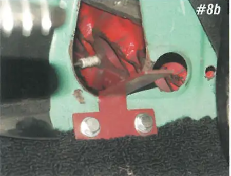
Image 8: When the new tilt column is installed, the column should be flush with the firewall and not as the original did. This allows clearance for a 605 or 670 steering box or the new type rack and coupler. With the tilt column flush with the firewall, the stock mast jacket clamp will no longer work. PIN 57-140799-1 lower column mounting bracket mounts on the inside of the firewall using the two factory mounting nuts on the firewall.
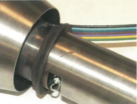
Image 9: Rubber seal PIN 05-13 at the top of the steering column finishes off the column to instrument bezel area on 1955-56 cars. Slide the seal on from the bottom of the column.
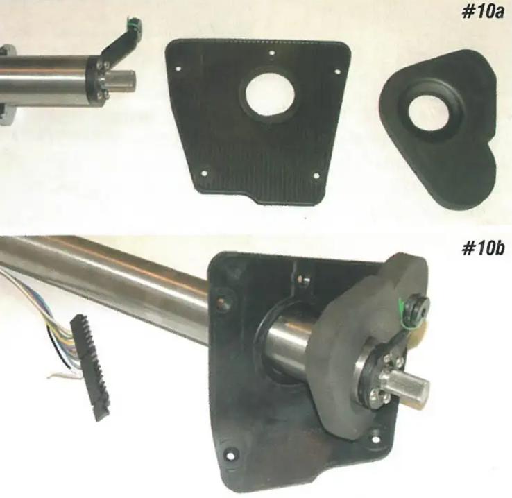
Image 10: At the bottom of the steering column, there is a foam rubber seal and rubber that seals the column to the firewall. The seals are different between automatic and standard transmissions cars. The foam rubber seal PIN 57-131195-1 is the same for the 1955-57 automatic columns. The rubber for the 1955-56 automatic columns is PIN 57-130860-1.
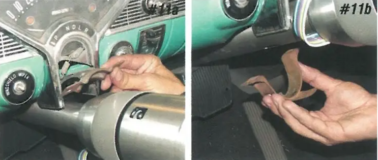
Image 11: The stock upper mast jacket clamp will hold the new tilt column in. Install the clamp, but leave it loose at this time.
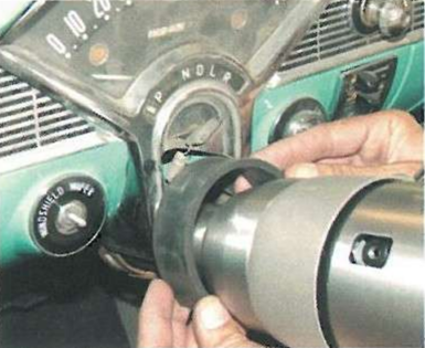
Image 12: On 1955-56 cars, there is a rubber strap PIN 57-130845-1 that wraps around the steering column. This holds the column tight in the upper mast jacket clamp. Slide the rubber down between the column and clamp, but leave the clamp loose.
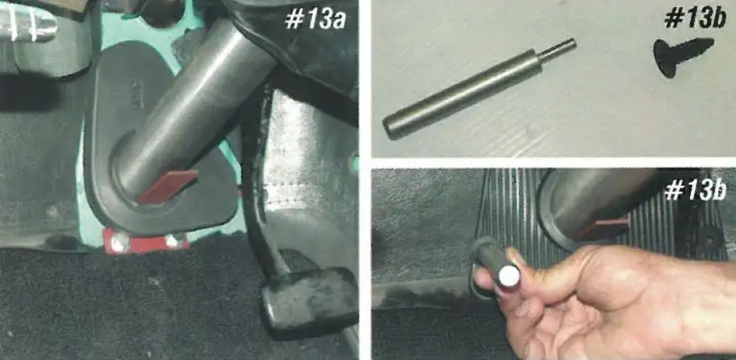
Image 13: Slide the foam rubber column seal and rubber down over the lower column mounting bracket. The stem on the lower bracket sticks up through the center hole on the seals. The seal is held to the firewall with five fasteners contained in PN 57-135506-1. To install the fasteners, use tool PIN 57-137036-1. This will the fastener in straight and tight.
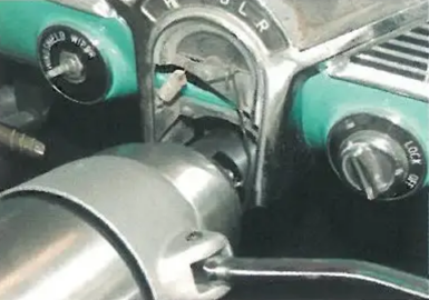
Image 14: Before tightening the upper and lower steering column clamps, adjust the steering column depth so that the loop on the shift tube lines up with the dash and the shift indicator wire PN 57-130990-1 can be connected.
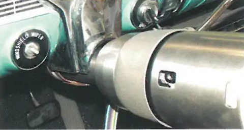
Image 15: With the indicator wire connected, the upper steering column cover can be installed.
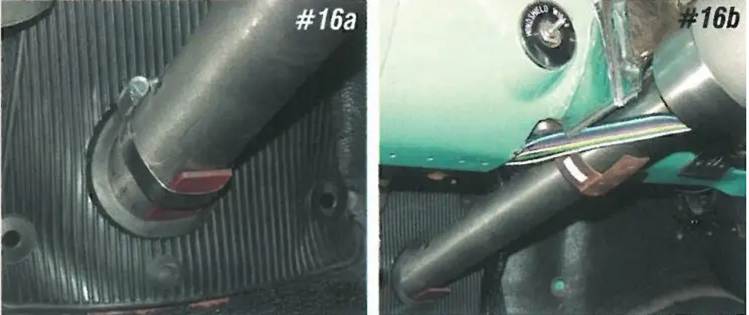
Image 16: The lower column bracket PIN 53-104 includes a stainless band clamp. With the column adjusted, tighten the band clamp and upper mast jacket clamp.
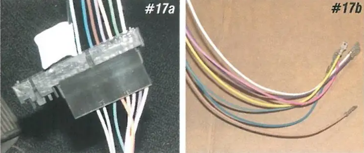
Image 17: The new tilt column includes a 1969-up turn signal switch. An adapter harness PIN 57-133752-1, 57-133753-1, or 57-133754-1 is available to connect the tilt column to the dash harness without doing any cutting or splicing.
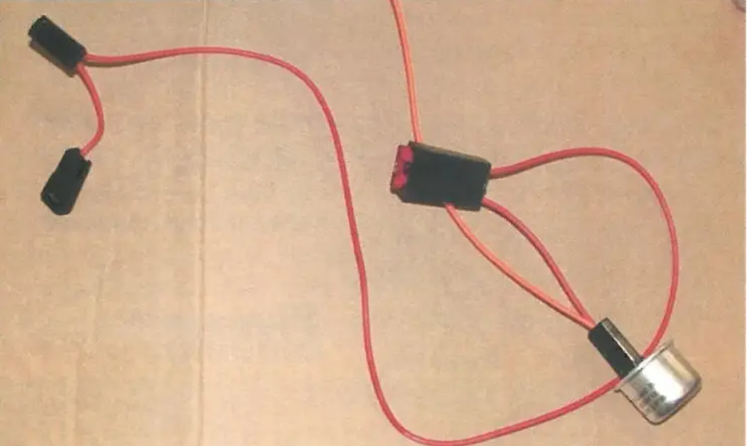
Image 18: The new column and adapter harness includes a four-way flasher. The red fused wire from the adapter harness should be connected to the "BAT" terminal on the ignition switch.
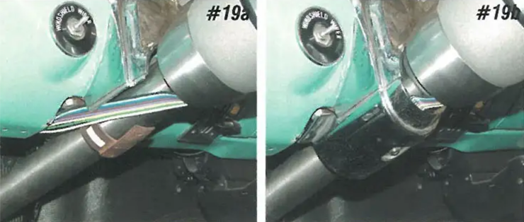
Image 19: The wires for the turn signal switch should be routed up the outside of the column on the left-hand side. Once the wires are routed, the lower mast jacket cover can be installed.
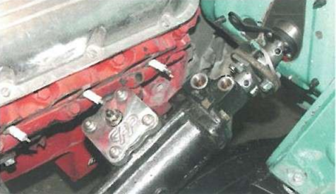
Image 20: The installed steering column is flush with the firewall giving you room for the coupler for a 605 or 670 steering box.
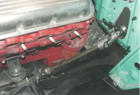
Image 21: The steering columns will also work with the new rack and shafts, so there is no longer a need for a special column just for rack and steering.
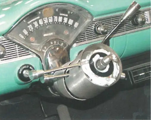
Image 22: The tilt steering columns come with billet knobs for the shifter, turn signal switch, tilt lever, and the four-way flasher.
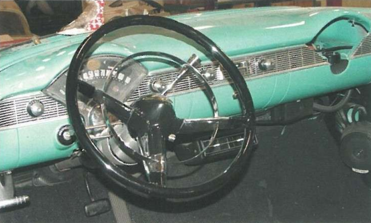
Image 23: The replacement 15" steering wheels PIN 53-144 (1955-56), PIN 57-159996-1 (1957), or PIN 57-170911-1 (1959-60) can be installed on the new tilt steering column using kit PIN 57-160378-1. Your original wheel can be installed using the same adapter. Or, any aftermarket wheel may be used with no adapter.