Eckler's Catalogs Available Now!
1955-57 Retrosound Model One Stereo Installation
We are happy to introduce another high-quality option in aftermarket stereos for your classic Chevy. These brand new designs from Retrosound USA combine ease of installation, super-compact design, and unequalled adaptability to all of today's high-tech gadgets:
- AM/FM Tuner With 24 Presets
- Front Panel USB Port For Flash Drive, MP3 Or WMA Playback
- Front Panel AUX Port For MP3 Player Charging
- Includes IR Remote
- 60 Watts Into 4 Channels
- Enhanced LCD Display Fits Stock Dash Opening
- Super Small 4" W x 6" D x 2" T Chassis Size Fits The Tightest Under Dash Situations
- Two-Year Warranty Against Manufacturing Defects
This stereo does not include the ability to control a CD as most stored audio now comes from an iPod or a similar unit. Our installation is in a 1955-56 car to show the use of the special dash speaker bracket now available. The 1957 cars do not require use of this bracket.
Parts List
- 38-222 1955 Retrosound Model One Stereo
- 38-223 1956 Retrosound Model One Stereo
- 38-224 1957 Retrosound Model One Stereo
- 38-226 200 Watt 6x9 Dash Speaker
- 38-227 200 Watt 6x9 Rear Deck Speakers w/Grilles
- 38-50 1955-56 Dash Speaker Bracket
- 06-28 1955-56 Dash Speaker Boot
Tools Needed
- Cutters
- Pliers
- Jig Saw
- Drill
- 3/16" Drill Bit
- Phillips Screwdriver
Time Frame
- 4 Hours
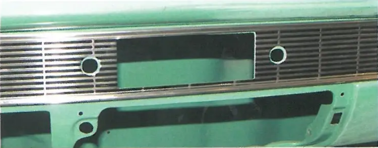
Image 1: It is much easier to remove and install a radio or stereo with the glove box and glove box door removed.
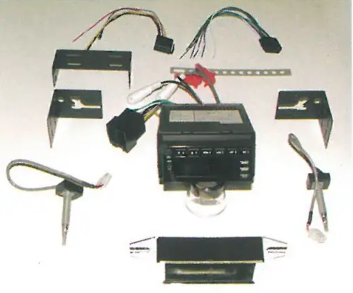
Image 2: The Retrosound Radio Model One PN 38-223 for the 1956 includes everything to mount the radio in the stock dash opening. The volume and tuner switches into the main body of the stereo. If you want to be creative and you are doing a custom dash, the switches can easily be relocated to the glove box or extend the wires and install them in a custom console.
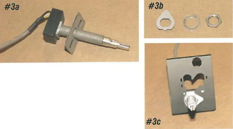
Image 3: The volume and tuner switches are held to the stereo's main body with elbow brackets. Install the rectangular onto the volume and tuner switches. The fit on the back side of the elbow brackets. Next, feed switch through the elbow bracket and using the locking washer, flat washer, and nut, anchor the switch to the elbow bracket. The bracket allows the switch to mount in various locations for different applications. On 1955-57 cars, the switch mounts in the outermost location.
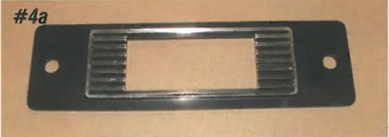
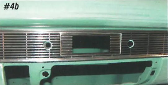
Image 4: The stereo includes a face to match the Bel Air dash trim for your year car.
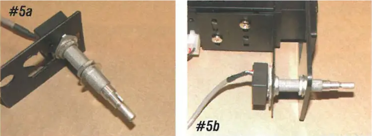
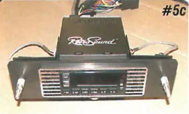
Image 5: Install another nut and flat washer on the switch stems. These nuts will be used to adjust the depth of the stereo in the dash. The elbow brackets are held to the main body of the stereo with two machine screws. The jacks from the volume and tuner switches into the side connectors on the radio. With the switches in install the face and adjust the nuts on the volume and tuner switches so that the face of the radio is flush with the face.
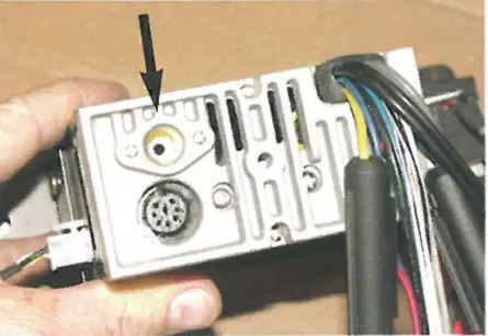
Image 6: On the back of the stereo you will find the female for the antenna.
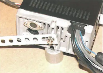
Image 7: A stud and nut is supplied to attach the rear mounting bracket. Once the radio is installed, the mounting bracket may be attached to the inner cowl (or speaker grille stud on '57 cars) to support the back of the stereo.
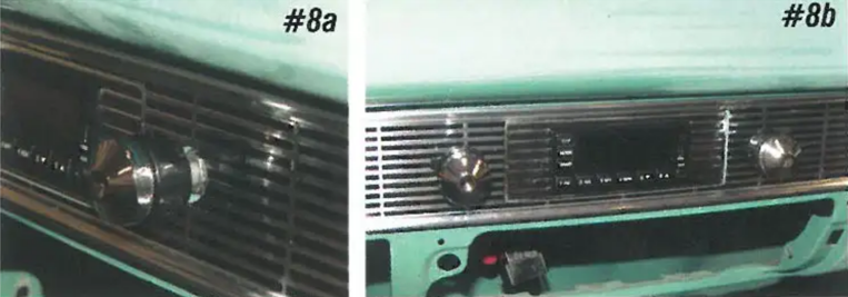
Image 8:The volume and tuner shafts are attached to the dash with another nut and flat washer. Once the radio is in, the year-specific knobs may be installed.
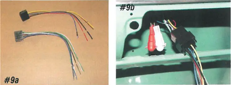
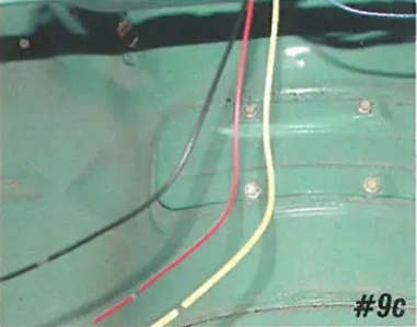
Image 9: There are two male jacks that into the single female jack on the radio. The red is the "power wire" and needs to be connected to a key-on 12-volt source. The black wire is the "ground wire" and needs to be connected to the body. The yellow wire is the "memory wire" for the station memory. This wire needs to be connected to a constant 12-volt source.
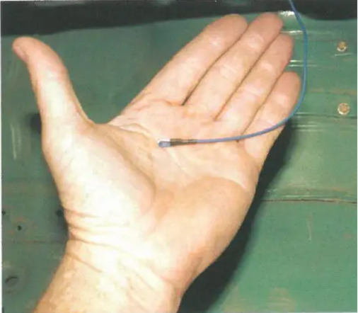
Image 10: The blue wire with the white tracer is the "power wire for an antenna". This wire would connect to the source wire for an antenna.
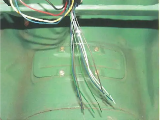
Image 11: The remainder of the wires are for the front and rear speakers, with each wire clearly marked for its function.
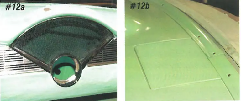
Image 12: The front speaker on 1955 and '56 cars mounts on the right-hand side of the dash behind the speaker grille. On 1957s, the front speaker is in the center of the dash, under the speaker grille.
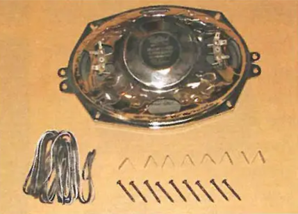
Image 13: The Restosound speaker PIN 38-226 is a 6x9" 3-way speaker with dual voice coils and will give you great stereo sound. This speaker features a super-slim 1-3/4" mounting depth for easy installation in tight spots and includes neodymium magnets that are 4X more than standard speaker magnets. It is wired to give you true stereo sound out of just one speaker assembly.
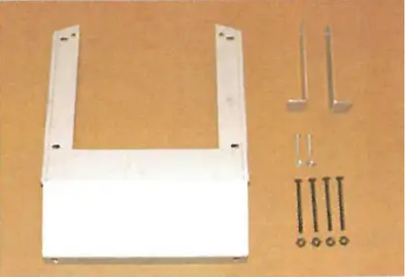
Image 14: If the stock '55-'56 speaker bracket is among the missing or if your car was never equipped with a radio, a replacement bracket PIN 38-50 is available. This bracket mounts to the dash using the stock mounting holes and unlike an original bracket, does not require modification.
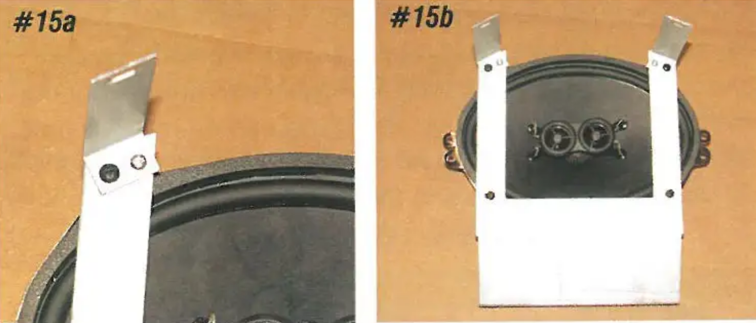
Image 15: The elbow brackets attach to the top of the speaker bracket with supplied hardware at a slight angle to match up the dash. The speaker is held to the speaker bracket with four screws and nuts supplied with the speaker.
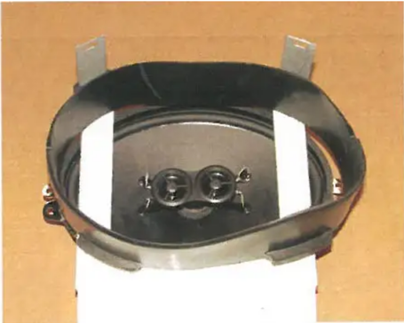
Image 16: The 1955 and '56 speakers use a rubber speaker boot PIN 06-28 to channel the sound through the dash speaker grille. The boot slides down onto the upper arms of the speaker bracket.
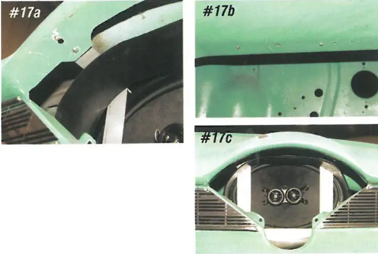
Image 17: The upper speaker bracket arms attach to the inner two holes behind the speaker grille using the supplied machine screws and nuts. The lower lip of the bracket attaches to the lower lip of the dashboard using the supplied machine screws and nuts. With the speaker installed, connect the appropriate wires from the stereo.
Image 18: Now to some real sound in your car, Retrosound also makes 6" X 9" rear deck speakers PIN 38-227 that can be mounted in the tray. These speakers have a chrome body and a molded grille with flames. This speaker is especially designed for use in classic cars and looks like it! The bezel can be left black or the interior color.
Image 19: Original cars only had a for a single rear speaker on the driver's side. Using a jigsaw, cut up the factory hole to an oval and cut an oval hole in the shelf in the corresponding location on the side. Using the speaker as a guide, drill four 3/16" holes for the mounting screws as required on the side. Also trim your cardboard tray to match the holes in the steel shelf. The speakers themselves mount to the bottom side of the steel shelf. Feed the mounting screws down from the top through the speaker bezel, tray, shelf, and speaker. Next, install the nuts on the screws and tighten. Complete the wiring to the rear speakers, and you now have a new top-quality and highly adaptable sound system for your classic!