Eckler's Catalogs Available Now!
1963 Gen IV Surefit Vintage Air Conditioning Installation Part II
One of the greatest upgrades that can be added to your Late Great Chevy is the addition of aftermarket air conditioning. In the next two issues of Chevy Classics, we will be showing you step by step installation of A/C on this 1963 Impala. I will be installing one of Vintage Air's new Gen IV SureFit systems on this Impala. The new SureFit system features electronic Servo motor controls with no cables; it mounts completely behind the dash. For years Vintage Air has been the leader in aftermarket air conditioning, be sure to contact your Ecklers sales representative for information on a Vintage Air unit for your year application. Now, follow along as we give this Impala a great new cool interior!
Parts List
- 40-213497-1 1963 Impala Vintage Air Gen IV SureFit Air Conditioning Kit For Cars Without Factory Air Conditioning
- 40-169483-1 1955-72 Double Groove Crankshaft Pulley
- 40-169485-1 1955-72 Small Block 348409ci Double Groove Water Pump Pulley
- 40-247616-1 1958-72 Small Block Air Conditioning Compressor Fan Crankshaft Pulley Belt
Tools Needed
- 3/8" Socket
- 1/2" Socket
- 1/2" Wrench
- Philips Screwdriver
- Straight Blade Screwdriver
- Grinder
- Vice Grips
- Electric Drill
- 1/8" Drill Bit
- 5/8" Drill Bit
- Silicone
- 1-1/4" Bi-Metal Hole Saw
- Cutter
Time Frame
- 16 Hours
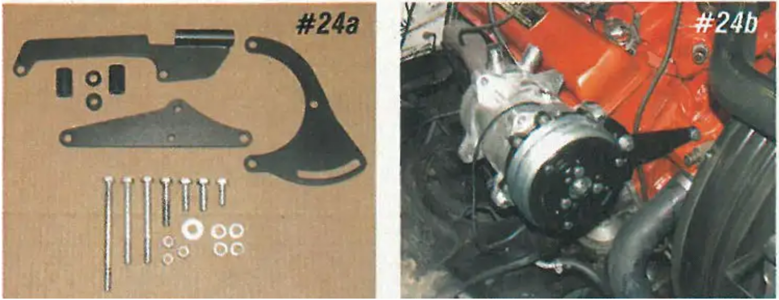
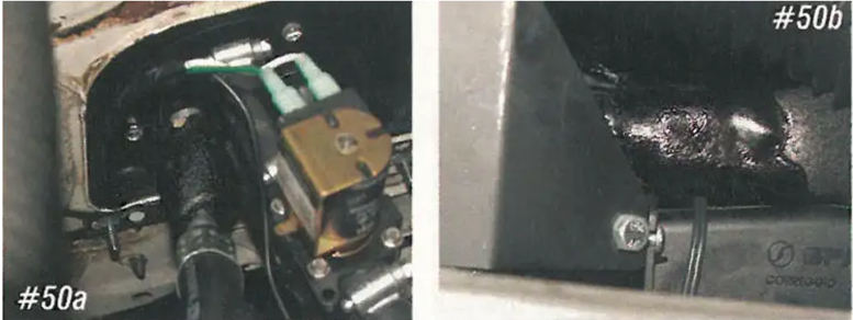
Using two of the exhaust manifold bolts and one water bolt, the compressor bracket will mount on the side of the engine. This bracket does not require the cylinder head to have any mounting holes.
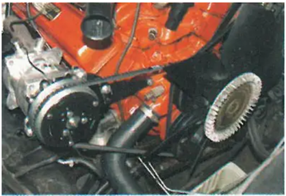
The air compressor belt PIN 541004 is routed around the forward groove on the water and the second groove on the crankshaft. If your engine has a single groove water pump, you will need to use a double groove (PIN 563652). If the crankshaft has a single groove, you will need to use a double groove (PIN 563650).
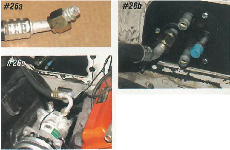
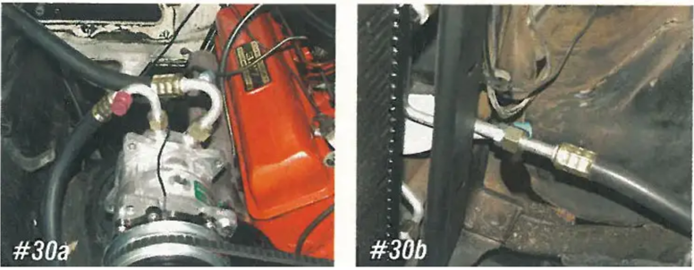
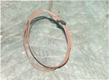
There is a large and a small rubber air conditioning hose. The larger hose will connect from the large fitting on the evaporator at the firewall to the larger fitting on the AC compressor. Install the supplied O-rings on the end of the hose, lubricate using the supplied lubricant, then install the hose. The large fitting at the firewall will receive insulation tape, but once again, we will not install the tape until we vacuum the system down and make sure we have no leaks.
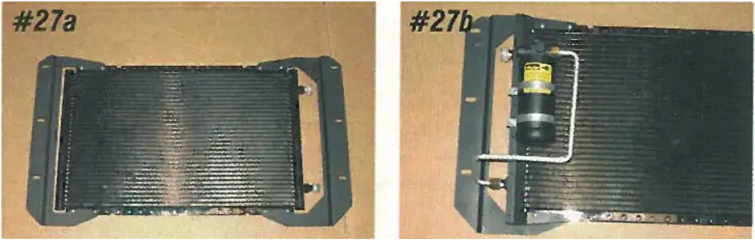
The condenser and receiver dryer will mount between the radiator and radiator core support with the inlet and outlet of the condenser on the side of the car. Install the condenser brackets on the backside of the condenser using the supplied machine screws and nuts. Next mount the receiver dryer, bracket, and aluminum tubes to the front side of the condenser on the side of the car.
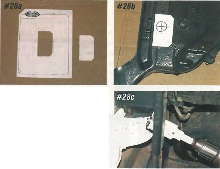
The two lines from the condenser will be routed through the radiator core support; these lines are down low and out of sight for a super clean look! A template is supplied with the kit to show the location of this core support hole. Cut the template out of the supplied 8-1/2" x 11" sheet and attach it onto the core support. The hole will be drilled just above the core support to frame mount. The core support does not need to be removed to drill the hole.
Raise the engine compartment about 2". With the condenser in install the supplied two-hole rubber grommet in the core support.
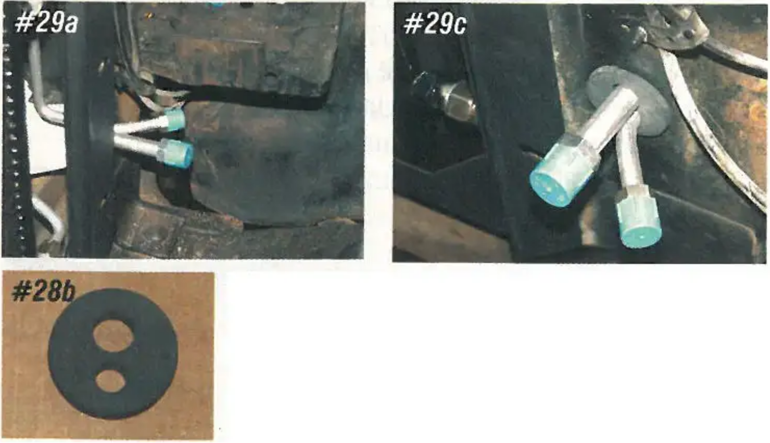
The smaller rubber air conditioning hose will connect from the air conditioning compressor to the larger line from the condenser. Install the supplied O-rings on each end of the hose, lubricate the O-rings, and install the hose.
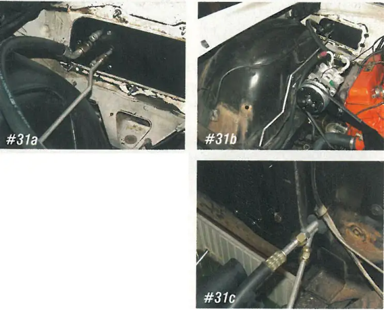
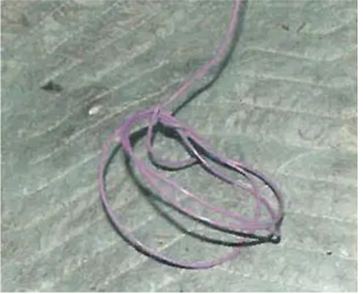
An aluminum line is used to connect the smaller fitting on the evaporator core, at the firewall, to the smaller fitting on the condenser. The line will run along the inner fender well just above the a-arm dust shield.
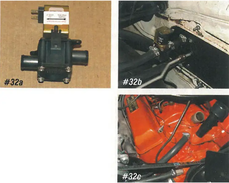
The heater control valve has an arrow that will face the heater core. The heater valve will install in the upper heater hose and connect to the heater hose nipple on the intake manifold. The lower heater hose will connect to the heater hose nipple on the water pump.
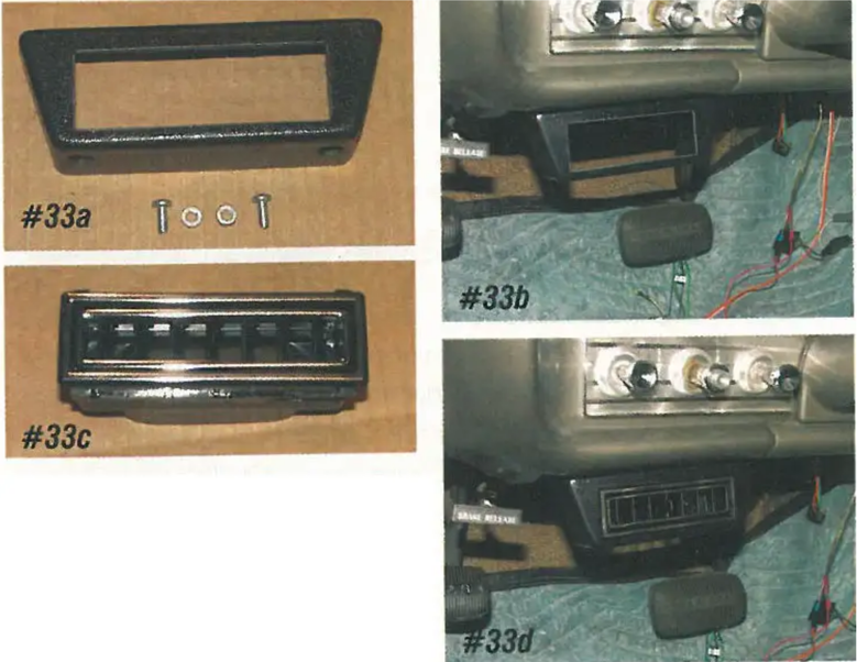
Now we'll move back inside the car. A single air conditioning vent will be installed to the left of the steering column. Using the bezel as a guide, drill two 3/16" holes and attach the bezel to the dashboard using the supplied machine screws and nuts. With the bezel in place, snap the vent into the bezel.
Next, install the center and side vent assemblies. The right-hand side of the bezel is held to the bottom of the dashboard using the original screw for the right-hand courtesy light. Again, using the bezel as a guide, drill two holes in the bottom of the dashboard and attach the rest of the bezel to the dashboard. With the bezel installed, install the three vent assemblies.
The evaporator housing has two 2" male outlets for the defroster manifold and four 2-1/2" male outlets for the four air conditioning ducts. Using figure 19 in the kit directions, connect the vents using the supplied duct hose.
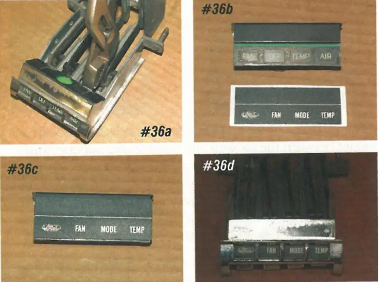
The new lens will be over the original heater/defroster lens to read FAN, MODE, and TEMP. Remove the stock lens assembly by straightening the tabs on the control. The new lens is a snap and stick. The lens will cover the stock lens and also attach to the front face of the light shield. With the new lens installed, install the assembly back into the control and twist the tabs holding the assembly in place.
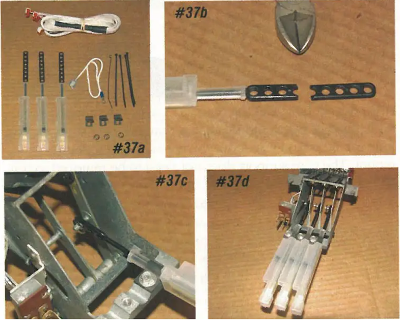
The original heater control will be used to control the new GEN VI air conditioning system. The SureFit conversion kit includes slider switches, switch mounting brackets, retaining clips, zip ties, and the wiring harness. First, using a pair of sharp cutters, shorten the switch arm so that there are three holes left in the arm. Next, anchor the body of the new switch to the stock heater control using the squeeze clamp. The arm for the new switch is held to the arm from the stock heater control with the new retaining clip. All three switches are the same, repeat the same on the other two switches. Make sure all three switches are oriented in the same direction.
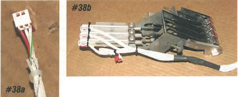
The control harness has four 3-wire male jacks; three of these jacks will be used. Each jack has a RED wire, a WHITE wire, and a WHITE wire with a colored chaser. Connect the jack with the GREEN chaser to the left-hand switch. Connect the jack with the YELLOW chaser to the center switch and connect the jack with the RED chaser to the right switch. The jack with the BLUE chaser will not be used in this application. With the jacks connected to the switches, use the supplied zip ties to anchor the jacks, switches, and harness to the stock control.

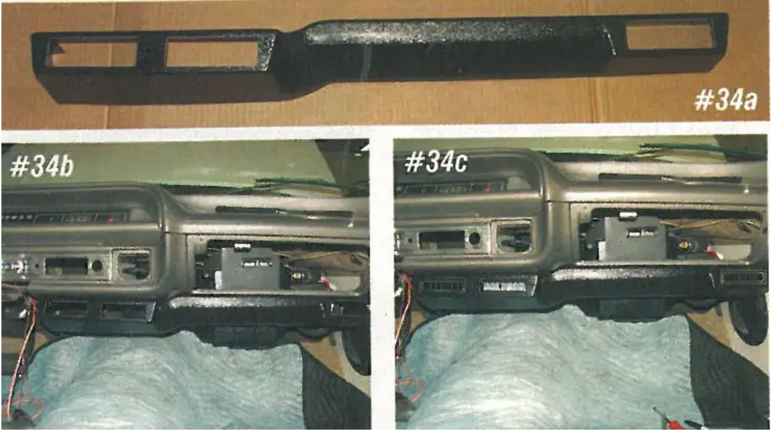
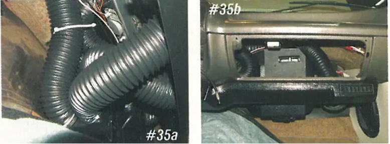
Install the converted control back into the dashboard and route the wiring harness across the dash to the evaporator unit. The male jack on the end of the wiring harness will plug into the right-hand female jack on the back face of the evaporator unit.
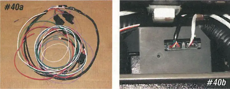
The main harness will plug into the left-hand female jack on the evaporator core. This harness also connects to the blower motor, the heater valve, the binary switch on the receiver dryer, a key on 12-volt source, to a ground, and a good constant 12-volt source.
The two female jacks with the red and white wires will plug into the male jack on the right-hand side of the evaporator core unit; this jack is for the blower motor.
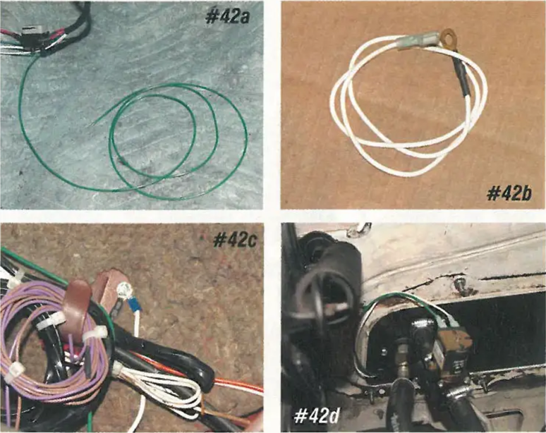
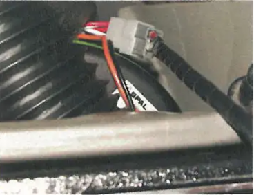
In the main harness, there is a green wire; this wire will attach to one of the terminals on the heater control valve. Also included in the main harness is a 10" long white wire with a female spade connector on one end and a round lug on the other end. This wire will connect to the other terminal on the heater control valve and to a good body ground. After connecting the round lug on the white wire to a good body ground, feed the white and green wire out through the grommet on the firewall filler, then connect the two wires to the heater control valve. A female spade connector is supplied for the green wire.
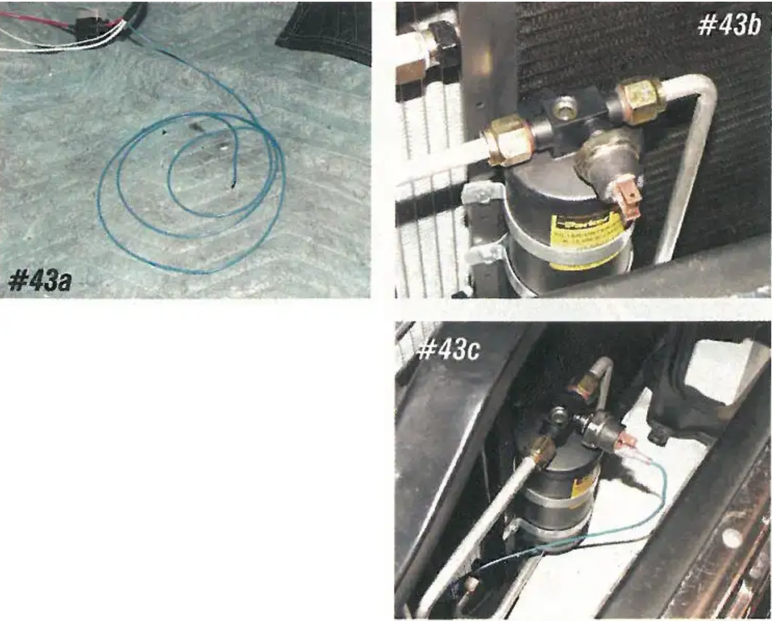
The blue wire from the main harness will connect to the binary switch on the receiver dryer. Remove the cap in the receiver dryer, lubricate the O-ring on the binary switch and install the switch. Feed the blue wire through the grommet in the firewall filler and connect the wire to one of the terminals on the binary switch using the supplied female spade connector.
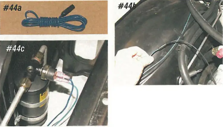
A blue wire is supplied in the main harness with a female connector on one end. The wire will connect to the air conditioning compressor clutch, and use the supplied female spade connector to the other terminal on the binary switch.
The brown wire is capped off on the end and is not used, zip tie this wire up under the dashboard.
The wire will connect to a "key on" fused 12-volt source. This wire can be connected to the original black wire that connected to the original blower motor switch or to the fuse box.
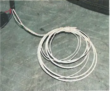
There is a large and a small white wire in the main harness; both of these wires will need to be connected to a good body ground.
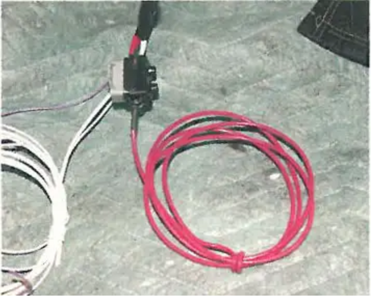
The large red wire in the harness is the main wire for the complete system. This red wire will need to be connected to the positive (+) battery terminal, or the large battery cable stud on the starter.
A 6" long white wire is included in the main harness kit. This wire has a female spade connector on one end and a round lug on the other. This wire will connect to a good body ground and the gray wire in the main harness marked "PRGM" momentarily to the computer that operates the GEN IV Air Conditioning system. Attach the round lug end to a good body ground, leaving the female spade connector UN-PLUGGED from the gray wire at this time.
Programming Procedures
- Step 1: Turn the ignition switch "ON" but do not start the engine.
- Step 2: Move the FAN, MODE, and TEMP levers on the control to their maximum positions.
- Step 3: Connect the gray wire to the white wire; the speed of the blower motor will change when step 3 is completed. It will take about 10 seconds.
- Step 4: With the key still on and the gray wire still connected, move all three levers to their minimum positions.
- Step 5: Next, disconnect the gray wire from the white wire; the blower motor speed will change again. Tape the end of the gray wire so there is no chance of it ever grounding out.
- Step 6: Next, the engine can be started, and the system can be charged.
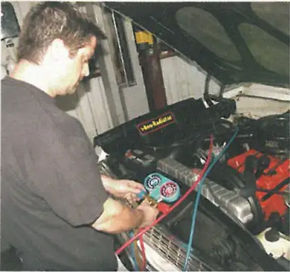
With the system programmed, it's now ready to be charged. First, the system will need to be vacuumed down with a vacuum pump. After you have determined there are no leaks in the system, wrap the large fitting at the firewall and the fitting large on the evaporator core with the insulation tape.
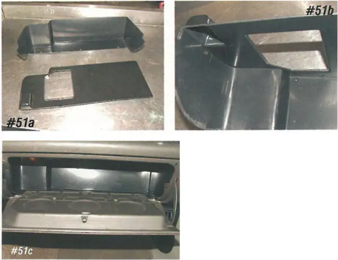
The stock glove box will no longer work due to the size of the evaporator unit under the dash. Vintage Air supplies a new smaller glove box. The top of the glove box is held to the bottom of the glove box with four self-tapping screws. First, assemble the glove box on the workbench, allowing the screws to cut holes in the top and bottom of the box. Now disassemble the box, install the bottom into the dash first, and then the top. Now attach the top of the box to the bottom of the box.
Next, have the system charged. Now enjoy that ice-cold air during the summer and the hot heater during the winter.
Nov. 2009